
Integrator multiplies 555 delay
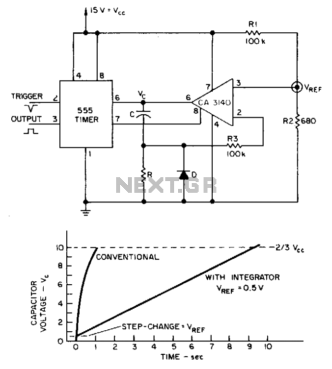
The 555 timer is a versatile integrated circuit widely used for generating time delays, oscillation, and pulse-width modulation. When configured as an integrator circuit, it can produce extended delay times, making it suitable for applications requiring longer timing intervals. This configuration involves connecting a capacitor to the timer's discharge pin, allowing the capacitor to charge through a resistor.
In this setup, the capacitor's charging time is significantly influenced by the values of the resistor and capacitor used. The integrator circuit modifies the standard operation of the 555 timer, allowing for a gradual increase in voltage across the capacitor. As the capacitor charges, the voltage rises until it reaches a predefined threshold, at which point the timer's output state changes. This transition can be utilized to trigger subsequent events in a circuit, such as turning on a relay or activating another component.
The longer charging time achieved through the integrator configuration is advantageous in applications where precise timing is crucial. It is essential to carefully select the resistor and capacitor values to achieve the desired delay, as they directly affect the time constant of the circuit. The time constant, τ (tau), is calculated using the formula τ = R × C, where R is the resistance in ohms and C is the capacitance in farads.
Using larger capacitors in conjunction with the integrator circuit can yield even longer delay times, but practical considerations such as size, cost, and response time must also be taken into account. Overall, the 555 timer configured as an integrator circuit is an effective solution for generating extended delay times in various electronic applications.Long delay times can be derived from a 555 timer with reasonably sized capacitors if an integrator circuit is used. The capacitor's charging time with an integrator circuit can be much longer than with a conventional 555-timer configuration. 🔗 External reference
Related Circuits
A 150 to 210 seconds analog delay timer project designed for controlling devices that require a minimum off timer before power can be restored, in order to prevent potential damage to the devices. This analog delay timer circuit can be...
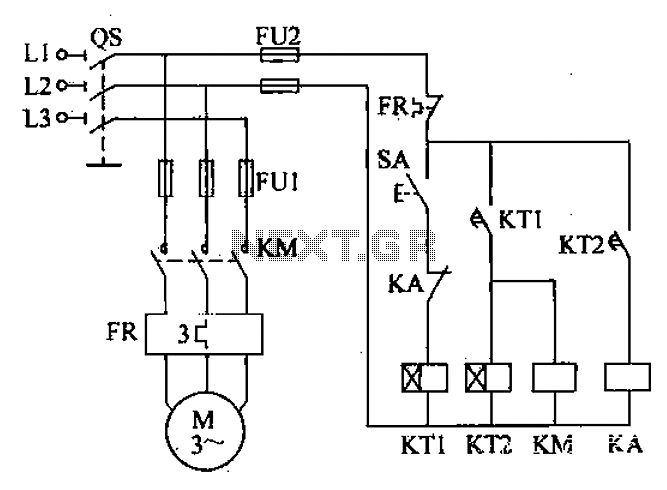
After the power switch is activated, the motor does not start immediately but instead has a specified delay period. This setup allows the machine to perform automatic intermittent lubrication control. The circuit for the motor boot delay and intermittent...
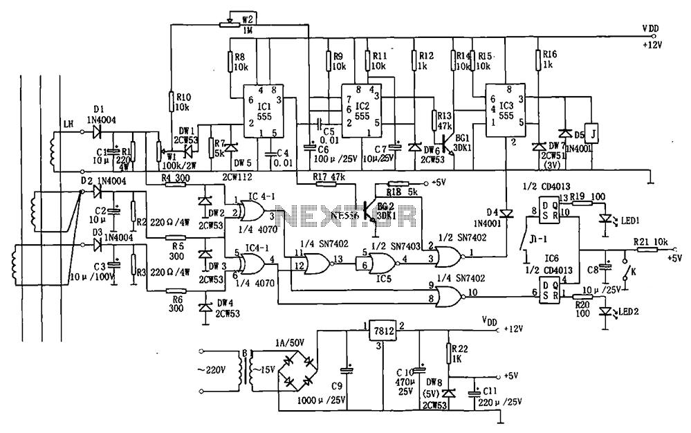
The electrical equipment overload and phase failure protection circuitry includes a +12V and +5V DC power supply, an AC transformer, voltage comparators, timers for blockade, a relay control circuit, and a phase loss protection circuit. The DC power supply...
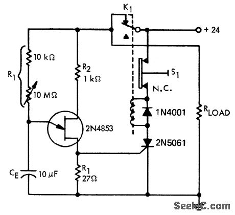
A time delay circuit utilizing a Unijunction Transistor (UJT). The maximum time delay is adjustable via a 10 MΩ potentiometer, allowing the time delay to be configured from less than one second to approximately 2.5 minutes, as referenced by...
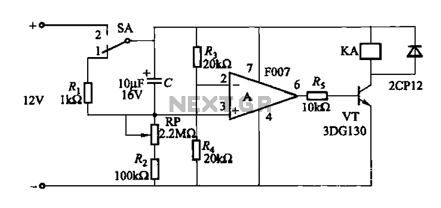
A delay circuit utilizing an operational amplifier functions as a comparator, providing high timing accuracy. The timer's delay range is from 1 to 30 seconds. The delay time is determined by resistors Ri, RP, and capacitor C. By adjusting...
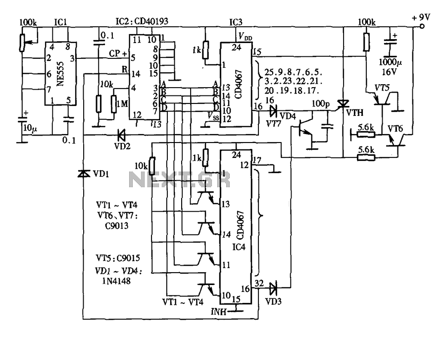
The lantern control circuit allows for the management of 30 outputs through an external driver circuit, specifically designed for water sports or large decorative lantern applications. The circuit features a control pulse generator, which regulates the lights, and an...