
Delay Timer
This analog delay timer circuit can be implemented using a combination of resistors, capacitors, and operational amplifiers to achieve the desired timing functionality. The core of the timer relies on the charging and discharging characteristics of a capacitor, which is controlled by a resistor network to set the time delay.
The circuit typically starts with a power switch that, when activated, begins the timing sequence. Initially, the capacitor is uncharged, and as current flows through the resistor, the capacitor begins to charge. The voltage across the capacitor increases gradually until it reaches a predetermined threshold level. This threshold can be set using a comparator or an operational amplifier configured as a Schmitt trigger.
Once the capacitor voltage surpasses the threshold, the output of the comparator changes state, signaling the control relay or transistor to activate the connected device. The timing duration can be adjusted by varying the resistor and capacitor values, allowing flexibility in setting the delay between 150 to 210 seconds.
To ensure reliability and prevent any potential damage to sensitive devices, it is crucial to incorporate additional features such as a power-on reset circuit, which ensures the system initializes correctly each time power is applied. Furthermore, a diode may be used to prevent back-emf from inductive loads when the relay is deactivated, protecting the circuit components.
In summary, this analog delay timer project not only provides a reliable method for controlling device power restoration but also emphasizes the importance of careful component selection and circuit design to ensure safe and effective operation.150 - 210 secs analog delay timer project for control of devices that need to have a minimum off timer before power can resume to prevent damage to the devices 🔗 External reference
Related Circuits
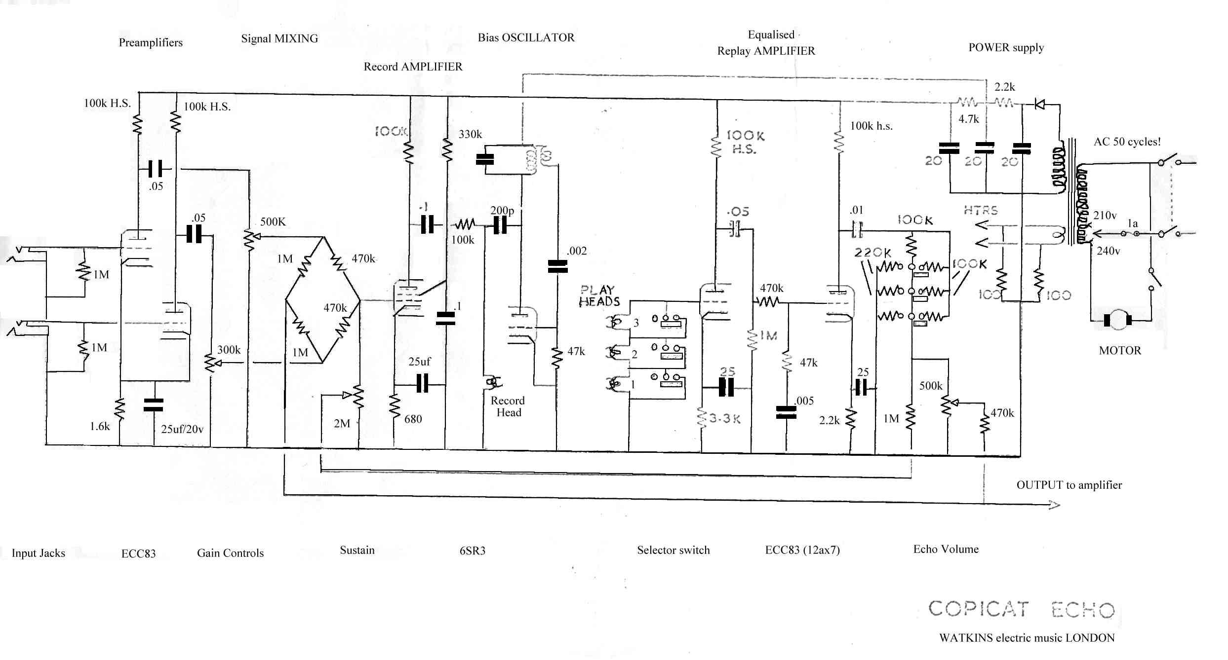
This is a request for assistance in designing a circuit for a tape delay unit. The mechanical components are functioning well, but the circuit integration remains a challenge. The tape heads used are cassette tape heads with a resistance...
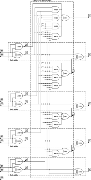
A 4-bit Carry Look Ahead Adder has 3 gate delays for all carry bits and 4 gate delays for all sum bits, whereas ripple adders have 7 and 8 gate delays, respectively. The 4-bit Carry Look Ahead Adder (CLA)...
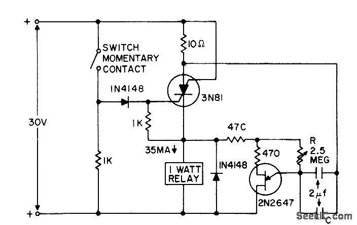
A switch applies a positive pulse to the gate of a silicon-controlled switch (SCS), activating it and supplying power to the relay load and UJT timing circuit. At the end of the timing interval, determined by the resistor-capacitor (R-C)...

The following method allows the timer to be triggered by a normally closed switch. This would be useful in applications such as intrusion alarms where the protection circuit is broken if a window or door is opened. Trigger Input...
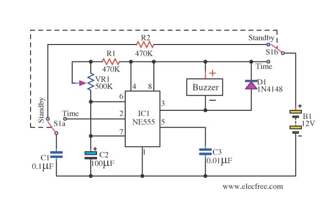
This is a simple and compact timer circuit (Egg Timer) using the IC 555. It features an alarm activated by a buzzer. This mini timer circuit is quite interesting and is referred to as the Egg Timer. The circuit utilizes...
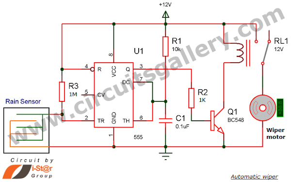
Have you seen Audi, Lexus, or Ford rain-sensing wipers and wondered how they operate in these vehicles? They are controlled by sensors located at the center of the windscreen, which detect raindrops and activate the wiper motor. The functioning...
Warning: include(partials/cookie-banner.php): Failed to open stream: Permission denied in /var/www/html/nextgr/view-circuit.php on line 713
Warning: include(): Failed opening 'partials/cookie-banner.php' for inclusion (include_path='.:/usr/share/php') in /var/www/html/nextgr/view-circuit.php on line 713