
Vehicle lights at night rendezvous controlled circuit

The circuit in Figure 13-50 operates by controlling the high beam lights (ELi and EL2) in response to the manual switch (SA). When the switch is activated, it sends a signal to the circuit that alternates the power supply to the high beams. This alternation is crucial for maintaining compliance with traffic regulations, which require that drivers do not dazzle oncoming vehicles with constant high beam usage.
The circuit may include additional components such as resistors to limit current flow, ensuring that the high beams operate within their specified voltage ratings. A relay could also be incorporated to handle the higher current required by the high beams, allowing the manual switch to control the relay instead of directly powering the lights.
Furthermore, the circuit can be designed with a timer or a microcontroller to automate the alternation process, enhancing convenience and ensuring compliance with regulations without requiring constant manual intervention. Safety features, such as diodes, may be included to prevent back EMF from damaging the circuit components when the relay is deactivated.
In summary, the described circuit effectively manages the operation of vehicle high beams in accordance with traffic regulations, enhancing safety during nighttime driving by ensuring that drivers can communicate their presence without compromising the visibility of other road users.Driving at night, when there is a vehicle rendezvous, according to traffic regulations prescribed distance should begin two vehicles alternately opening and closing the big lig ht, while OFF, showing the wide lights or low beam lights to ensure the safety of vehicles pass through. The circuit shown in Figure 13-50 to play this role. Figure, ELi and EL2 for the big lights, SA manual switch.
Related Circuits

This is a water sensor circuit design based on a Conductive Liquid Level Sensor. This single-chip circuit is compact and simple. It is an AC-excited fluid level sensor, which uses alternating current to provide biasing for the sensor probe,...
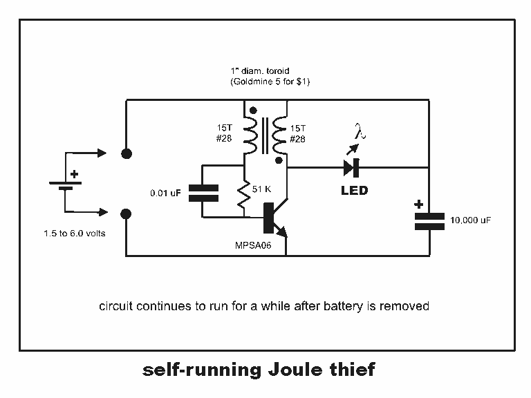
Professor Steven E. Jones' circuit demonstrates an 8x overunity. The concept of overunity refers to a system that produces more energy than is consumed, effectively achieving a coefficient of performance greater than one. In the context of Professor Steven E....
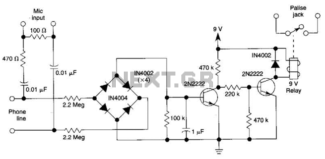
The DC voltage on a telephone line typically ranges from 45 to 50 V when on-hook and drops to around 6 V when off-hook. This circuit utilizes the voltage drop to activate a relay, which in turn controls a...
This light sensor switch circuit enables the automatic activation of a lamp when ambient light levels are low, such as during nighttime. The circuit keeps the lamp illuminated for a predetermined duration. When transistors T4 and T5 are activated,...
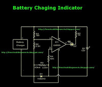
This is a battery charger indicator circuit diagram. When the battery is charging, it is indicated by an LED. This circuit can be used with a 12V battery with a charging current of less than 1A. The battery charger indicator...
Assistance is needed for the design of a timing circuit intended to activate a spark plug every 10 or 20 revolutions of a shaft. The timing circuit for firing a spark plug at specified intervals can be designed using a...