
ir emitter 38khz

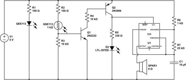
The circuit utilizes a 555 timer configured in astable mode to generate a square wave output at 38 kHz, suitable for driving the IR LED. The 555 timer's output is connected to the anode of the IR LED, while the cathode is connected through a current-limiting resistor to ground. The choice of the resistor value is critical; a lower resistance allows for higher current through the LED, thus increasing its output power and range. The IR receiver is designed to detect the modulated IR signals, and its output is connected to a red LED through a 1k resistor to indicate when a signal is received. The receiver's gain characteristics are influenced by the nature of the incoming signal, with AGC mechanisms allowing for optimal sensitivity during bursts of data while reducing sensitivity to continuous signals.
The power supply circuit is essential for stable operation; the 7805 voltage regulator ensures that the circuit receives a consistent 5V from the 9V wall wart, with bypass capacitors placed close to the regulator to filter out noise. The timing capacitor in the 555 circuit influences the duty cycle of the output signal; careful selection of capacitor and resistor values will determine the frequency and pulse width of the output signal.
Testing and troubleshooting this circuit may involve experimenting with different resistor values for both the IR LED and the timing capacitor to achieve desired performance characteristics. Additionally, ensuring all connections are secure and verifying the integrity of components will contribute to the overall reliability of the circuit. The insights gained from this project may enhance understanding of IR communication principles and the operation of the 555 timer in various applications.I`ve built a 555 based oscillator to drive ir led at 38khz. I`ve got the circuit wired up and I`ve used my meter on the duty setting to read that it is indeed generated a 38khz signal. I`ve also wired up a modulated IR receiver, the one from radio shack set to 38khz. I`ve verified it`s working by pointing my TV remote at it. I`ve hooked up a red l ed to the output pin of the receiver and it lights up and flashes when I do this. The red led lights up occasionally especially if I move the receiver back and forth horzontally. I`ve checked for loose wires [this is all on a couple of bread boards], the led always lights up when I blast it with my remote. Oh I`m using a 5v source from a wall wart [the radioshack one that you can select the output voltage for] connected to a 7805 with a couple of capacitors.
The power source circuit i bought and soldered together, it fits standard breadboards [solar-robotics] so hopefully its okay. One thing I did notice is on the timing capacitor, if I short the two pins of the capacitor with my finger, the receiving led lights up as if its working fora second or two then goes out.
This works if I repeat the process touching the capacitor. I`m at work and don`t have the IR receiver circuit handy but I`ll post it when I get home. I don`t recal if I`m connecting the red led to ground or to +5V. The IR receiver itself is directly connected to ground and the +5V rails. I have a 1k resistor connected from the output pin to a regular red LED to indicat the presence of a signal. Do all modulated IR receivers have a auto gain mechanism I`ve seen so many of these little pulsed IR led circuits for simple obstacle avoidance that I`m beginning to wonder if I`ve missed something totally or my receiver just isn`t designed for my intended purpose.
The output high of the 555 is only +3. 6V if its power supply is +5. 0V. The voltage across the IR LED is about 1. 3V so the remaining 2. 3V is across the 470 ohm current-limiting resistor which gives a current of only 2. 3V/470 ohms= 4. 9mA. Most IR rerceiver ICs are designed to reduce their gain when they detect continuous 38kHz from a compact fluorescent light bulb. Their gain is at max when the IR pulses are in bursts of data. If you replace the 470 ohm current-limiting resistor in your IR sender with 39 ohms then the current pulses in the IR LED will be about 52mA and the range will be much more.
The datasheet for most IR receivers show a resistor feeding +5V to it then a capacitor to ground. It won`t work properly without the resistor and capacitor. Here is an IR receiver circuit from Vishay`s datasheet: I checked when I got home this evening and I happen to be using a 120 ohm resistor instead of the specified 470 ohm resistor. My wall wart is set to 9V, and the 7805 is putting out a steady 5 Volt. At this point I think its the gain issue that people mentioned earlier in the thread. If I move my hand over both the emitter and receiver [both point up], the led lights up [the led connected to the receiver], connected to the receiver for a second then it goes out.
This is repeatable. Not sure where this leaves me, perhaps the brief signal is all the train guy needs to drive a relay or for a little robot to reverse direction or turn right etc. Ok so its the AGC. Winson the Ir receiver I am using is from Radio shack, they only sell one type AFAIK. 38kHz Infrared (IR) Receiver Module - RadioShack. com Audioguru - Thanks for you response and your suggestions are good I will attempt to modify the circuit as you specified.
Will make me more familiar with the 555 in any event! 🔗 External reference
Related Circuits
This circuit detects when a tube is empty and pulses a piezo buzzer at 5-second intervals. It is currently operational with a 5V supply on a breadboard but needs to be adapted for a 12V supply from a wall...
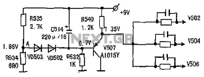
The common-emitter amplifier circuit V502, V504, V506 is designed to generate a static potential bias voltage through an emitter follower configuration, as illustrated in Figure 3. The active filter is formed by components V507, VD502, and VD503. The emitter...
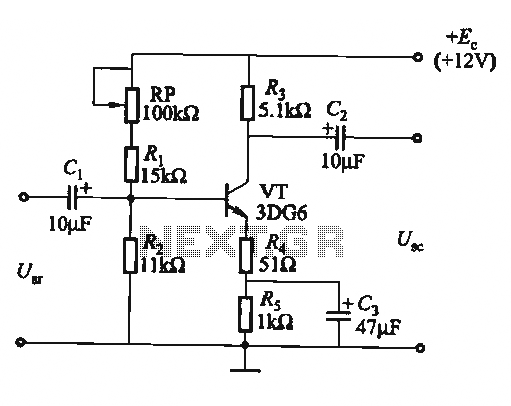
The circuit is a bias circuit for automatic stabilizers that maintains a stable quiescent operating point with good thermal stability. It utilizes a three-pole tube with an NPN type transistor, characterized by a small Iceo. An adjustment potentiometer, RP,...
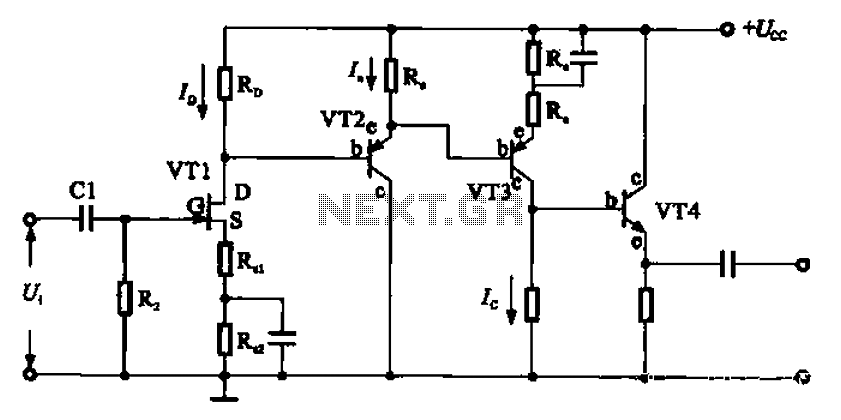
A combination of a common-source grounded emitter amplifier and a common emitter amplifier. The input impedance of the common emitter amplifier is in the range of 1.03 fl. Directly connecting the FET drive can be challenging; however, utilizing an...
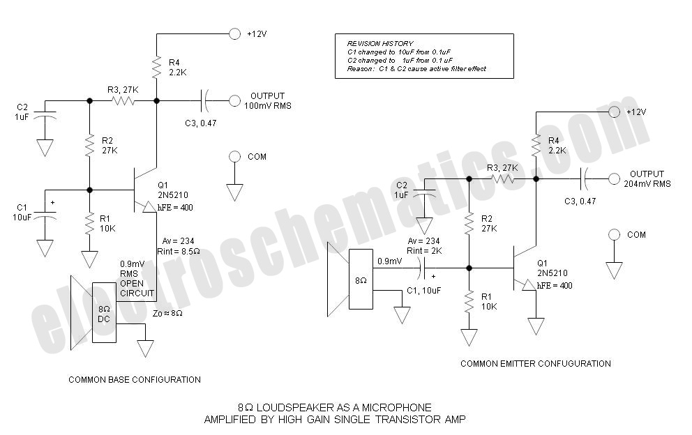
Single Transistor Amplifier Revisited Part 3, Common Base vs Common Emitter Configuration, Update One nagging question that I have long had is this: How do... The single transistor amplifier is a fundamental building block in electronic circuits, and its configurations—common...
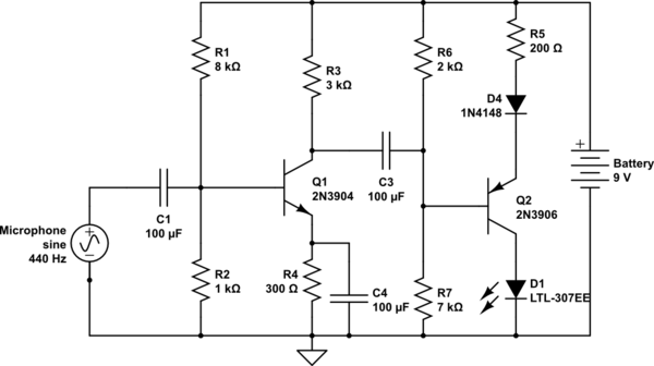
The circuit takes input from a microphone to power an LED, which remains off in ambient sound conditions and brightens with increasing noise levels. The peak voltage produced by the microphone is proportional to the sound levels. The microphone...