
Ir Receivers

The circuit in question appears to involve a receiver module designed for detecting signals, likely within a specific range of light conditions. The performance of the module is contingent upon the ambient lighting, with incandescent lighting providing stable operation, while fluorescent lighting introduces instability at close distances.
The receiver module likely employs a photodetector that converts light signals into electrical signals. This conversion process is sensitive to the wavelength and intensity of the incoming light. Incandescent lighting, which emits a continuous spectrum of light, allows the module to function effectively. In contrast, fluorescent lighting, which can produce sharp peaks in certain wavelengths, may lead to interference or noise in the output signal.
The mention of a power supply is critical, as improper voltage levels can lead to false output pulses. It is essential to adhere to the manufacturer's specifications regarding power supply requirements to ensure reliable operation.
The output from the receiver module is likely fed into an oscillator circuit, which may be responsible for generating a specific frequency based on the input signal. The reference to "Oscillator Output - C" suggests that the output configuration is designed to match a particular characteristic that aligns with the manufacturer's testing parameters. This output may be used to trigger additional components in a larger system, such as microcontrollers or other processing units, which further interpret the signals received.
In summary, the operation of this receiver module is significantly influenced by the type of lighting environment, and careful attention to power supply specifications is crucial for optimal performance. The design considerations for the circuit should include filtering mechanisms to mitigate the effects of unstable output under varying lighting conditions.Before using this or a similar device, their data sheet should be read carefully and any power supply recommendations should be followed to prevent false output pulses. The receiver module used for this test worked very well under all levels of incandescent lighting. # Under very bright or direct florescent lighting the output became unstable. Usually at distances of less than 1 meter from a 48 watt fixture. # Based on data sheet information, Oscillator Output - C most closely resembles the manufactures tes 🔗 External reference
Related Circuits
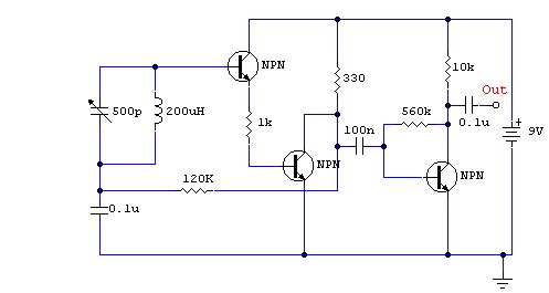
This is a compact three-transistor regenerative receiver with fixed feedback. It is similar in principle to the ZN414 radio IC, which is no longer available. The design is simple, and the sensitivity and selectivity of the receiver are good....
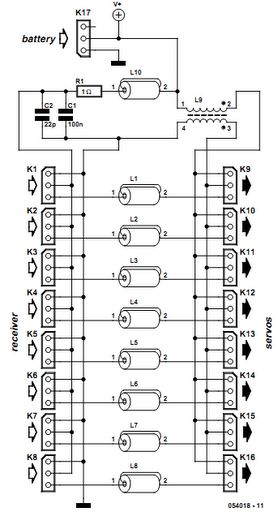
Receiver interference is a common issue among model builders. Preventive measures, such as ferrite beads fitted to servo cables, are frequently employed in larger models and electrically driven models to prevent the cables from acting as antennas and radiating...
The regen is basically an oscillator circuit with a gain control that allows the user to adjust the feedback to a point just below oscillation or, quite often, just above the critical level such that a small oscillation is...
Firstly because of the modulation process we generate at least two copies of the intelligence plus the carrier. For example consider a local radio station transmitting on say 900 Khz. This frequency will be very stable and held to...
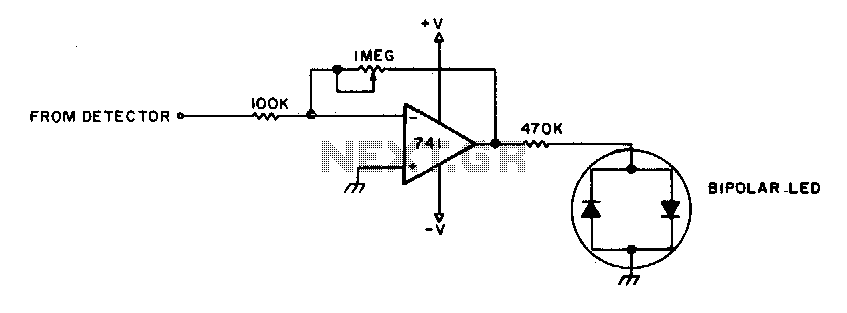
To adjust, tune into a station and adjust the I"M pot for a null. Then ask the station to modulate and fine-tune so modulation peaks do not light the LEDs. Stations are properly tuned when neither LED is lit. The...
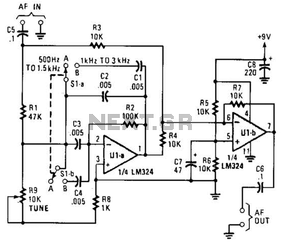
The notch filter can be integrated into nearly any receiver to attenuate a specific frequency by over 30 dB. This filter is particularly useful for diminishing heterodynes and whistles. A notch filter, also known as a band-stop filter, is designed...