
IR Remote Control Extender var 5 Circuit

The Mark 5 Infrared Repeater circuit is designed to extend the range of remote control signals, allowing devices to be operated from greater distances or through obstacles. This circuit typically consists of an IR receiver, a microcontroller or amplifier, and an IR transmitter.
The IR receiver detects signals from remote control devices and converts them into electrical signals. These signals are then processed by the microcontroller or amplifier, which boosts the signal strength. The amplified signal is subsequently transmitted by the IR transmitter, which emits infrared light that can be detected by the intended device.
Key components of the Mark 5 circuit may include a photodiode or phototransistor as the IR receiver, a low-noise operational amplifier to enhance the signal, and a high-efficiency IR LED for transmission. The circuit may also incorporate a power supply section, which could utilize a voltage regulator to ensure stable operation.
The enhancements in the Mark 5 over the Mark 1 may include improved sensitivity of the receiver, which allows it to capture weaker signals, and a more robust transmission capability, which increases the effective range. Additionally, adjustments to the circuit layout may reduce interference and improve overall reliability.
This circuit can be utilized in various applications, such as controlling home entertainment systems, HVAC units, or other devices that rely on IR remote controls. The design considerations for the Mark 5 may also include the use of filters to minimize ambient IR noise and optimize performance in diverse environments.The latest addition to my collection of Infra Red (IR) Repeater circuits. The Mark 5 is a much improved version of the Mark 1 circuit and has increased range. 🔗 External reference
Related Circuits

An infrared (IR) remote control circuit for managing home appliances can be constructed using a Decade Counter CD4017, a 555 Timer, and a TSOP1738 infrared receiver. This circuit allows users to control home devices with a standard remote control,...
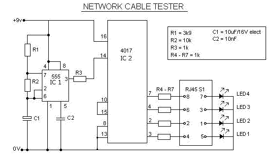
This is a multifunction RJ45 network cable tester designed for testing network cables (RJ45) and telephone cables (RJ11). It is cost-effective and user-friendly. The tester determines whether a network cable is a crossover or straight type by illuminating a...

This simple mock flasher LED simulates the indicator of a sophisticated alarm system. It can be placed in doors, gates, and vehicles to confuse intruders. The mock flasher LED circuit is designed to mimic the flashing behavior of a typical...
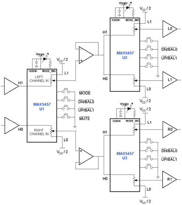
Application circuit using three stereo digital potentiometers to control volume, balance, and fader in a four-speaker configuration with a push-button interface. The application circuit utilizes three stereo digital potentiometers, which are essential components for managing audio levels in a multi-speaker...

Preamp circuits are used in front of an RF oscillator to create an RF transmitter that is highly sensitive to sound. A microphone preamp must provide stable gain. Preamp circuits play a crucial role in the functioning of RF transmitters...
The frequency of a transistor oscillator is regulated by two different lengths of nickel tubing, each containing two coil windings. One coil functions as a driver, while the other serves as a pickup to generate feedback voltage necessary for...