
Irregular Flasher

The circuit design utilizes the 4011 NAND gate IC to create two independent multivibrator circuits, each capable of generating square wave outputs at different frequencies. The configuration employs two RC timing networks: one associated with R2 and C2, and the other with R5 and C5. The frequency output of each multivibrator can be calculated using the provided formula, which indicates that the frequency is inversely proportional to the product of the resistance and capacitance values.
In this setup, the output behavior of the LEDs D1 and D2 is directly linked to the oscillation states of the multivibrators. When the output of the first NAND gate (IC1, pin B) is high, indicating a logic '1', LED D1 is activated. Conversely, when IC1, pin C is high, D1 is off. This complementary behavior ensures that D2 will illuminate when D1 is off, and vice versa, creating a visual indication of the oscillation states.
The choice of using low-current LEDs is critical due to the limitations of the NAND gates in sourcing or sinking current. Standard LEDs typically require more current than the 4011 can provide, thus low-current alternatives are necessary to ensure proper functionality without damaging the IC.
The circuit is designed to operate efficiently at a supply voltage of 12 V, where the calculated current consumption is approximately 5 mA. However, the 4011 IC is versatile enough to function within a supply voltage range of 5 to 15 V, allowing for flexibility in various applications. For scenarios requiring higher current outputs, the HC series of CMOS ICs can be employed, which are designed to operate at lower supply voltages while providing enhanced current capabilities. The HC7400 part number identifies the quad NAND gate within the HC family, which can be utilized for similar circuit designs requiring robust performance at lower voltages.Two multivibrators with different frequencies can be built using the NAND gates of a 4011 IC. If the output of IC1. B is positive with respect to IC1. C, LED D1 is on. As the levels of IC1. A and IC1. D are exactly opposite, D2 is always on when D1 is off, and the other way around. The two oscillators have different frequencies, which are determined by the values of R2/C2 and R5/C5 respectively according to the formula f0 = 1 G· (1. 4 RC) With the given component values, the frequencies are 2. 2 Hz and 7. 2 Hz. Low-current LEDs should be used, since the CMOS IC cannot sink or source sufficient current for normal` LEDs. The values of series resistors R3 and R6 are suitable for a supply voltage of 12 V, in which case the current consumption of the circuit is around 5 mA.
However, in principle the 4011 can be operated over a supply voltage range of 5 15 V. Higher currents can be provided by the HC family (supply voltage 3 6 V) or the HCT family (5 V). Incidentally, the part number of the quad gate IC in the HC family is HC7400. 🔗 External reference
Related Circuits
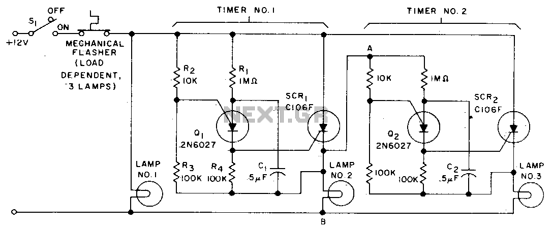
When the turn signal switch (SI) is closed, lamp #1 is activated, and capacitor C1 charges to the triggering voltage of transistor Q1. Once the anode voltage on Q1 exceeds its gate voltage by 0 V, Q1 transitions to...

This circuit adopts the rather unusual Bowes/White emitter coupled multivibrator circuit. The oscillation frequency is about 1Hz and is set by C1 value. The LED starts flashing when the photo resistor is scarcely illuminated. The onset of flashing can...
This circuit functions as a low-frequency warning device. The output from the oscillator generates a square wave signal, which is utilized to operate lamps or small relays. The circuit alternately flashes two incandescent lamps. The low-frequency warning device circuit typically...
Ideal for operating 3 to 24V DC existing on-circuit lamps. This circuit was designed to provide continuous light for lamps already wired into a circuit. The circuit is intended to facilitate the operation of existing DC lamps that are integrated...
The LED flasher circuit operates by flashing an LED using only a 1.5-volt power supply. Typically, a power supply of more than 2 volts is required for an LED to function. The LED flasher circuit designed for operation at 1.5...
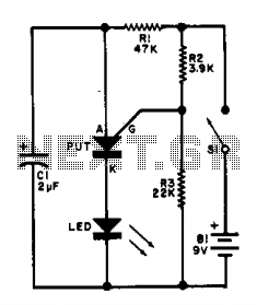
This flasher circuit functions as a relaxation oscillator, with capacitor C1 discharging periodically through the LED when the Programmable Unijunction Transistor (PUT) is activated. The flashing rate is approximately 100 times per minute, based on the specified component values. The...