
Jogging Timer

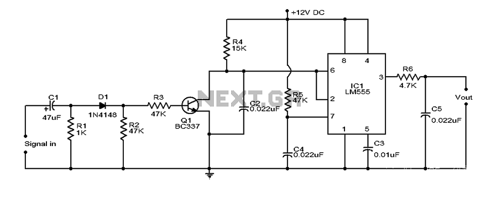
The described circuit functions as a timer with an adjustable duration for auditory feedback, specifically designed for jogging intervals. The heart of the circuit is a microcontroller or a timer IC that manages the timing intervals. The rotary switch, SW1, allows the user to select the desired time delay, which ranges from 1 to 9 minutes.
In each position of the rotary switch, a different resistor or capacitor configuration may be employed to set the timing interval. For instance, in position 1, the circuit might utilize a specific resistor-capacitor (RC) time constant that corresponds to a 1-minute delay. As the switch is rotated to subsequent positions, the time constants would be adjusted accordingly to produce delays of 2, 3, up to 9 minutes.
The Piezo sounder serves as the output device, providing audible cues to the user. The microcontroller or timer IC triggers the sounder to emit three short beeps at the end of each selected interval. This operation can be achieved using a simple transistor switch to drive the Piezo element, ensuring that sufficient current is supplied to produce a clear sound without damaging the microcontroller.
Power supply considerations for the circuit should ensure compatibility with the components used, typically requiring a low-voltage DC source. Proper decoupling capacitors should be included near the power pins of the microcontroller or timer IC to filter out any noise that may affect performance.
Overall, this circuit design combines user-friendly interface elements with effective timing and output capabilities, making it suitable for applications where interval timing and auditory feedback are essential, such as in fitness routines.This circuit was developed since a number of visitors of this website requested a timer capable of emitting a beep after one, two, three minutes and so on, for jogging purposes. As shown in the Circuit diagram, SW1 is a 1 pole 9 ways Rotary Switch. Setting the switch in position 1, the Piezo sounder emits three short beeps every minute. In position 2 the same thing happens after a 2 minutes delay, and so on, reaching a maximum interval of 9 minutes in position 9.
🔗 External reference
Related Circuits
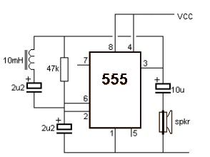
A simple metal detector circuit can be implemented using a 555 timer chip. The schematic diagram illustrates that this project requires only a few external electronic components. The metal detector circuit utilizing a 555 timer operates in astable mode, generating...
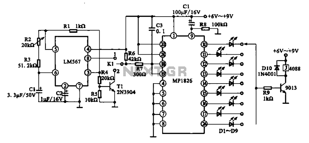
A precision circuit utilizing the LM567 timer, specifically the MPI826, where the LM567 functions as a dual-band oscillator. The MP1826 serves as a divider in the circuit, allowing the output signal from the LM567 to achieve extended timing. The...
The following circuit illustrates a Cat and Dog Repellent Timer Circuit Diagram. Features include a high-output ultrasonic transmitter and the use of a standard 555 timer. The Cat and Dog Repellent Timer Circuit is designed to emit high-frequency ultrasonic sound...
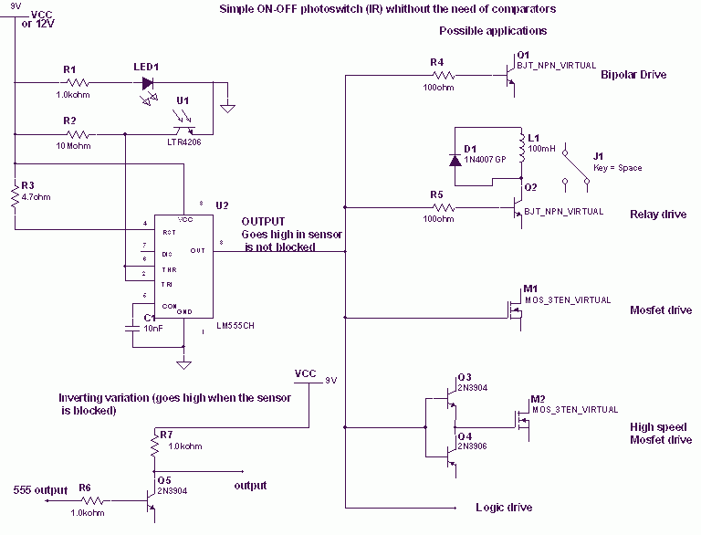
When the phototransistor is struck by IR light it conducts and the voltage between the 1Mohm resistor (arbitrary) and the phototransistor drops from VCC to lower values. When the voltage drops lower than VCC/3 the 555 is triggered and...
This document provides an overview of a simple circuit diagram for frequency (F and V) voltage conversion. It describes a digital frequency meter circuit primarily based on the LM555 timer IC, which is commonly used in various applications, including...
A TV remote jammer circuit using the NE555 timer IC. This device allows users to watch their favorite TV channels without interruptions, as it prevents others from changing the channel using a remote control when the circuit is activated....