
Joule Ringer
Warning: Undefined array key "extension" in /var/www/html/nextgr/view-circuit.php on line 468
Deprecated: strtolower(): Passing null to parameter #1 ($string) of type string is deprecated in /var/www/html/nextgr/view-circuit.php on line 468

Testing has been conducted with a coil tower constructed from 24-gauge wire, measuring 9.5 inches in height and 3 inches in diameter, made from a modified Pringles can. Initial tests involve wrapping 24-gauge bifilar wire around the lower quarter of the coil tower. The presence of metal rings at the top and bottom of the can may detract from energy efficiency, so it is recommended to remove them and make longitudinal scores on the inside of the can. Thicker wire with fewer turns has been observed to yield better results.
The circuit utilizes an MJE13007 transistor, known for its robustness during testing. Alternatives such as the 2N3055, TIP3055, or TIP31 are also considered viable. However, the MJE13007 may overheat in this application. The circuit has been noted to emit stray emissions, potentially violating radio regulations, with the ability to light a blue LED from a distance of up to 50 cm using an Avramenco plug. At 12 volts, this distance extends to one meter, indicating a need for shielding.
Using a ferrite core coil at frequencies between 3 to 6 kHz may reduce concerns about stray emissions, although audible noise could still be an issue. Experience with power transistors has provided insights into small signal transistors, which behave differently by amplifying signals rather than simply switching them on or off. This characteristic allows for reduced voltage and amperage draw without saturation.
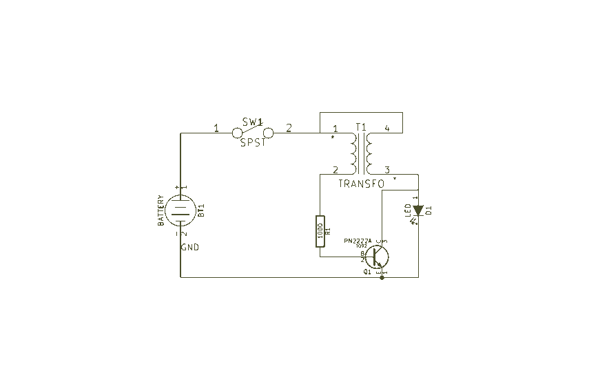
The circuit schematic for the Tesla Lamp has been updated to eliminate a non-functional trigger coil. High voltage feedback from the bulb now triggers the base, akin to the design in Laser Saber’s JRV2.0. The use of a switching 3055 power transistor yielded similar but slightly dimmer results compared to previous configurations. Replacing an LED with a 1N4148 diode resulted in increased brightness in the bulb. The primary coil now encompasses the full length of the secondary coil, which consists of 500 turns in the secondary and 25 turns in the primary.
The advantage of using small signal amplifier transistors like the 2N2222 or 2N4401 is that the CFL can illuminate at 2 volts and increase in brightness with rising voltage. Conversely, as the battery depletes, the circuit continues to emit light. While the design may not be groundbreaking, it is notable for its simplicity and ability to operate across a wide range of DC voltages without requiring specialized components.The nicety of air coils: one can build them at home rather easily and they seem to swing at a higher inaudible frequency above 100 KHz. May be the frequency comes down once really huge coils achieve an inductance comparable to ferrite core coils.
But I hope that with a careful design one can build a more delicate circuit with a frequency above 100 KHz. I have some smaller CFLs which only need 3 to 5 Watt at the 220V mains and seem to glow bright enough to be useful with 0, 5 to 1 Watt on a super Joule Ringer type circuit. A retro lamp has to be dimmer to underline the 19th century atmosphere Hi folks, Hi conrad, i tried the setup, though I think the 24 gauge main tower coil is too thick of a gauge wire to get the needed high voltage for the cfl.
I happen to just finish a coil tower yesterday, though it has 24 gauge wire and is 9-1/2" tall X 3" diameter, it`s a pringles chips can with metal bottom removed. I`m going to make some tests starting with 24 gauge bifilar wrapped around bottom 1/4 of coil tower and see how it goes with your wiring setup, then try some different things just to see.
Also those rings at the top and bottom of the can. They will suck the energy out before you can say "Pip" Get rid of those and make some scores in the inside of the can length wise. it should do, but i would even try to peal that inner layer off if you can. Ive seen setups with thicker wire and fewer turns do the job. Give it a try before you unwind. ;] I finished rewinding with 30 awg wire and am using speaker wire for primary, just trying different wires and types, i think its 20 or 22 gauge, stranded of course.
@Lynxsteam: at the moment I use the MJE13007 transistor (because it takes a lot of abuse when testing strange coils). Others are using the 2N3055, and I guess TIP3055 or TIP31 should work as well. I suspect the MJE13007 overheats to much in this type of circuit, so it probably is not the best choice.
The other day it came to my mind that this circuit will not fulfil the requirements of "radio regulations" because it emits a lot of stray emissions. I can light a blue LED with an Avramenco plug (no connection, just a piece of wire as an antenna and my body as virtual ground) up to 50 cm away from the coil.
With 12 Volt operation the distance goes up to a meter. Some shielding will have to be done eventually. Using a ferrite core coil at e. g. 3 to 6 KHz will be not so critical in this respect, although the audible whine can be a nuisance. I have always used the power transistors for this type of experimenting but recently learned a lot about small signal transistors from my work with wind turbine controllers. Whereas with power transistors being fully on or off, small signal transistors are amplifiers and are non-linear in the way they follow voltage.
So by reducing voltage we can also reduce amperage draw. They also don`t saturate the way power transistors do. I updated the circuit schematic for my Tesla Lamp. The trigger coil wasn`t doing anything so I got rid of it. Its the HV feedback off the bulb that triggers the base as in Laser Saber`s JRV2. 0. I tried a power transistor, switching 3055 and the results were about the same but slightly dimmer. I replaced the LED with a leaking diode 1N4148 and the bulb runs brighter. Also, the primary runs the full length of the secondary. 500 turns secondary, 25 turns primary. The nice thing about a small signal amplifier transistor like a 2N2222 or 2N4401 is the CFL will light dimly with 2 volts and get brighter as the voltage goes up. Or conversely, as the battery runs down the circuit still gives off light. There is nothing spectacular about this device. But what I like is that you can make one very simply with no exotic components and run it off a wide range of DC voltages.
The nice thing about a small signal amplifier transistor like a 2N2222 or 2N4401 is the CFL will light dimly with 2 volts and get brighter as the voltage 🔗 External reference
Related Circuits

This circuit does not utilize a transformer or complex integrated circuits (ICs). Instead, it requires two transistors and additional components. The circuit was discovered inadvertently while exploring Colin Mitchell's Talking Electronics website, which offers a wealth of examples and...
Easy Joule Thief Soldering Kit from MakersBox on Tindie The Easy Joule Thief Soldering Kit is designed for educational purposes, allowing users to learn about basic electronics through hands-on experience. This kit includes all necessary components to assemble a Joule...

A simple yet effective circuit to generate a POTS-compatible ringing voltage can be constructed using National Semiconductor's LM4871 audio amplifier IC along with a dozen passive components. This circuit produces a sine-wave output of 1 W at approximately 70...
The circuit consists of four main components: an indicator LED, a hand-wound coil, a 1k resistor, and a 2N4401 transistor. The coil is made from solid core telephone wire, with a total of 14 turns wound around the core,...
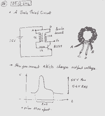
A simple voltage boost circuit known as the Joule Thief has been identified for construction. The Joule Thief is a minimalist boost converter designed to extract energy from low-voltage sources, such as depleted batteries, and increase the voltage to a...
Using modulated rectangular waves of different time periods, the circuit presented here produces ringing tones similar to those produced by a telephone. The circuit requires four astable multivibrators for its working. Therefore, two 556 ICs are used here. The...