
knight Rider

The circuit design employs a microcontroller-based architecture to create a versatile light effect reminiscent of the iconic KITT scanner. The PIC16F84A microcontroller serves as the central processing unit, programmed to manage the LED activation sequence. The choice of a microcontroller over discrete components such as the CD4017 counter provides the opportunity for software updates and modifications to the light pattern without physical changes to the circuit.
The power supply design includes a 7805 voltage regulator, ensuring that the microcontroller operates within its specified voltage range. This regulator takes an input voltage from 7 to 12 V and outputs a stable 5 VDC, which is essential for reliable microcontroller operation. For applications where space is at a premium, a zener diode could replace the voltage regulator, though this may introduce variability in voltage stability.
The external RC oscillator configuration is a crucial aspect of the microcontroller's timing mechanism. The use of a 10k resistor in conjunction with the capacitor (if included) sets the frequency of operation. The omission of the capacitor, while simplifying the circuit, necessitates careful consideration of the impact on frequency stability. The LED activation period of 0.14 seconds is adjustable by changing the resistor value, allowing for customization of the light effect speed.
The software design is bifurcated into two versions. The basic assembler version provides a straightforward implementation of the light effect with binary states. In contrast, the extended C version introduces PWM to create a gradient effect in the trailing LEDs, enhancing the visual appeal of the light pattern. This PWM capability allows for finer control over LED intensity, contributing to a more sophisticated light display.
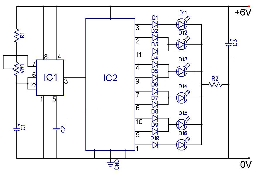
The design philosophy emphasizes flexibility, with the microcontroller enabling the possibility of future enhancements and variations in the light effect without necessitating hardware changes. The introduction of a secondary circuit using the PIC12F629 microcontroller further illustrates the commitment to compact design and efficiency, accommodating a minimal number of external components while maintaining functionality. Overall, this light computer design exemplifies the advantages of microcontroller-based systems in creating dynamic and adaptable electronic displays.I have created a light computer that generates an effect like the scanner of the car KITT in the TV series Knight Rider. You can see a visualization of the effect in the image below: Many circuits on the Internet are built with a CD4017 counter IC.
I myself chose to use a microcontroller for this job: the PIC16F84A. A microcontroller increases the complexity but it allows you to build a very flexible light computer. The circuit can be kept very small, this was a requirement for this circuit. The circuit can be powered by a DC voltage between 7. 12 V. I used a 7805 regulator to create a stable 5 VDC voltage. It you want to keep the circuit very small you could use a zenerdiode for the stabilization. The microcontroller is oscillated by an external RC oscillator. The capacitor was left away. This can be done but it decreases the stability of the frequency. The resistor has a value of 10k. I did some measurements on the circuit and the LEDs are active for a period of 0. 14 seconds. To change the speed you can simply change the value of resistor R1. You could also add a capacitor between OSC1 and the GND. A basic version in the assembler language. It runs the knight-rider light effect with only two possible output states: ON or OFF. Download the assembler source code. An extended version in the C Language. This software generates a little trail before and after the active LEDs. The intensity of the LEDs in the trail is lower. This is done by implementing some sort of PWM (pulse width modulation). Download the High-TECH C source code. A question you might ask yourself is why this circuit should be made with a PIC microcontroller. You get a 555 and a 4017 counter IC for less money. With them the same effect can be achieved. I have to admit the microcontroller is overkill for this kind of application. But one big advantage about microcontrollers is they are very flexible: the complete light effect can be changed without having to change the electronic circuit. To demonstrate this I have written the extended version of the software (see previous topic - extended version with PWM control).
I also designed a second hardware version of this circuit, with the PIC12F629. This is a DIL-8 microcontroller that uses very little place. You don`t need any external parts other than LEDs and resistors. 🔗 External reference
Related Circuits
This simple circuit drives six LEDs in a Knight Rider scanner mode. Power consumption primarily depends on the type of LEDs used, especially when utilizing a 7555 (555 CMOS version). The Knight Rider scanner circuit is designed to create a...
IC4, C1, R1 and R2 are used for the clock pulse which is fed to both the counters IC2 and IC3 Pin 14. IC1 is a Flip Flop and is used as a switch to enable either IC2 or...
The speed of the display can be adjusted as desired. The output from the 555 timer is directly connected to the input of a CD4017 decade counter. The input of the counter is referred to as the CLOCK line...
The circuit consists of two building blocks. The first is a square wave oscillator made up of two transistors in a multivibrator arrangement and the second is a CD 4017 decade counter IC. The multivibrator contains two extra components...
The bi-directional sequencer utilizes a 4-bit binary up/down counter (CD4516) and two "1 of 8 line decoders" (74HC138 or 74HCT138) to create the well-known "Night Rider" display. A Schmitt Trigger oscillator generates the clock signal for the counter, with...
The 555 timer IC is connected for Astable Operation, the clock pulses are fed to the 4017 IC via the 10K resistor. The 4017 is a 10 stage counter, each of the outputs is connected to the appropriate LED,...