
LCD 3 wires

The LCD display integration using a shift register provides an efficient means of controlling the display with fewer pins, thereby conserving resources on microcontroller boards such as Arduino. The schematic typically includes connections for the shift register's data output (Dout), clock (CLK), and strobe (STR) signals, which facilitate the transfer of data to the LCD. The four data lines from the LCD (DB[0] to DB[3]) are connected to the corresponding output pins of the shift register, allowing for 4-bit data transmission.
The initialization sequence for the LCD is crucial for proper functionality. It begins with a delay to allow the LCD controller to power up, followed by a series of commands sent to configure the display mode, including setting the interface to 4 bits, specifying the number of display lines, and selecting the font size. The commands are sent using the `LcdCommandWrite` function, which handles the control signals and data transmission through the shift register.
The library provided includes functions for initializing the LCD, sending commands, and outputting data. The `sendByteOut` function takes care of shifting the data out to the register and triggering the strobe signal to latch the data into the LCD. It's essential to manage timing carefully, as delays are interspersed between commands to ensure the LCD is ready to receive new instructions.
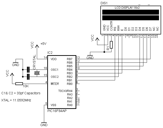
In summary, this approach to interfacing with LCD displays using a shift register not only simplifies the wiring process but also enhances the versatility of microcontroller applications by minimizing pin usage while maintaining functional integrity. The documentation and code provided serve as a valuable resource for developers looking to implement similar solutions in their projects.This post is based on the work made previously by tomek in wiring LCD displays using 4 bits. The basic idea is to group the 7 pins that are needed to drive the LCD in only 3 using a shift register. This is a cheap alternative to serial LCDs. The schematic shows that wiring the LCD is a simple operation. It has been drawn in a way that makes it pos sible to develop this as part of a single sided PCB including a variable resistor to control the LCD`s contrast. Note that the pin-out of the LCD module may differ slightly from the pin-out depicted; some LCD modules have pins 15 and 16 on the left side, before pin 1.
As part of the Arduino Miniconf at linux. conf. au 2012, freetronics released the pebble v2 with identical Shift Register wiring than this page, and Attendee Marc MERLIN wrote a NewLiquidCrystal driver for this hardware: This driver should work for all LCD3Wires based hardware, and was based on the excellent work from Francisco Malpartida who modified the original LiquidCrystal library to provide support for different hardware drivers. His work is available here:. This is the work Marc based his driver on to provide full LiquidCrystal support to LCD3Wires hardware by writing LiquidCrystal_SR_LCD3.
cpp. Below is the original code originally written to talk to this hardware setup. It does not work out of the box with arduino 1. 0, and the library is much less featureful than LiquidCrystal. It is left here for historical purposes. Also available is a library: Attach:LCD3WireLibrary. zip. To remain command-compatible with the LCD4BitLibrary, this library does not contain the number-formatting code which is included in the code below. To get the original version working on IDE 1. 0 you have to copy/paste WConstants. h and wiring. h from IDE 0023 into arduino-1. 0hardwarearduinocoresarduino To get the 0. 2 version working on IDE 1. 0 do the same thing as above and then make the following changes in the LCD3WireLibrary. h and LCD3WireLibrary. cpp files: /* LCD display with 3 wires * - * * based on previous examples by Tomek. * This program will use shiftout to send * data to a shift register with strobe that * will transfer the serial into parallel data * * the pin-out for LCD displays is standard and there is plenty * of documentation to be found on the internet.
* * (cleft) 2007 Dojodave for K3 and SADI * * */ // pins to be used on Arduino int led = 13; int count = 0; int Dout = 11; int STR = 12; int CLK = 10; // the Qx in the order they are connected on the chip int DI = 1; int RW = 2; int Enable = 3; int DB[] = { 7, 6, 5, 4}; void LcdInit() { delay(100); // initialize LCD after a short pause // needed by the LCD`s controller /////////// 4 pin initialization LcdCommandWrite(0x03); // function set: // 4 pin initialization delay(64); LcdCommandWrite(0x03); // function set: // 4 pin initialization delay(50); LcdCommandWrite(0x03); // function set: // 4 pin initialization delay(50); LcdCommandWrite(0x02); // function set: // 4 pin initialization delay(50); LcdCommandWrite(0x2C); // function set: // 4-bit interface, 1 display lines, 5x7 font /////////// end of 4 pin initialization delay(20); LcdCommandWrite(0x06); // entry mode set: // increment automatically, no display shift delay(20); LcdCommandWrite(0x0E); // display control: // turn display on, cursor on, no blinking delay(20); // clear display, set cursor position to zero LcdCommandWrite(0x01); delay(100); LcdCommandWrite(0x80); // display control: delay(20); } void sendByteOut(int value) { shiftOut(Dout, CLK, LSBFIRST, value); digitalWrite(STR, HIGH); delayMicroseconds(10); digitalWrite(STR, LOW); } void LcdCommandWrite(int value) { int i = 0; int value1 = 0; int control = 0; // stores DI and RW digitalWrite(STR, LOW); // set the strobe LOW control = value >> 8; // get the control signals DI and RW control <<= 5; // shift the control signals to the left value1 = value; value1 >>= 4; //send the first 4 data 🔗 External reference
Related Circuits
The resistor between basis and collector (around 47k) is to be individually set according to transistor characteristics. Without PIC in socket at the collector should be 2.5 V. The circuit described involves a transistor configuration where a resistor, typically valued...
LCDs are available in various configurations, with the 16x2 matrix display being the most popular. This article demonstrates the interfacing of an ATmega16 microcontroller with an LCD by displaying a simple character. In this project, the LCD operates in...
This is a practical expansion board designed for a PIC development board, intended for DIY use with a 16x2 alphanumeric LCD. The expansion board connects to the PIC development board, providing LCD support, which is essential for numerous projects...

The schematic for this tutorial is illustrated below and includes all necessary components for the tutorial to function. The PIC programming circuitry is not included, as it is assumed that the PIC is either programmed externally or that the...

LCD2USB is an open source/open hardware project. The goal of LCD2USB is to connect HD44780 based text LCD displays to various PCs via USB. LCD2USB was meant to be cheap and to be made of easily available parts. It...
This resource provides a variety of PIC Microcontroller tutorials that cater to both beginners and advanced users. These tutorials enable individuals to gain expertise in microcontroller programming and circuit design without the need for costly embedded system courses. The tutorials...