
LED Bar Off Indicator

The circuit operates on the principle of feedback control to manage power consumption effectively. The LM3914 IC serves as the primary driver for the LED bar display, which is typically used for visual representation of signal levels. The inclusion of the additional LED indicator (D11) is a clever design choice that enhances the functionality of the circuit by providing a clear indication of the operational state.
The configuration of transistors T1, T2, and T3 is crucial for the current management system. When all the bar LEDs are off, the absence of voltage across R3 keeps T1 in a non-conducting state, allowing T2 to remain on. This state enables T3 to provide a constant current output through D11, ensuring it lights up and signals that the circuit is still active. Conversely, when any of the bar LEDs (D1 to D10) are illuminated, the voltage across R3 increases, turning T1 on and switching T2 off. This action effectively disables T3, which reduces the current through R2 and thus decreases the overall current draw of the circuit.
The use of a low current draw for the indicator LED (1 mA) is particularly advantageous in battery-operated applications, as it minimizes power consumption while still providing essential feedback about the circuit's status. The design demonstrates a thoughtful balance between functionality and efficiency, making it suitable for a variety of applications where power conservation is a priority. Overall, this indicator circuit is an effective solution for ensuring clear operational feedback while managing power consumption effectively.The simple indicator presented in this article may be combined, in principle, with any circuit that contains an LED bar display driven by a Type LM3914 IC. It ensures that an LED will light when all LEDs driven by the LM3914 are out. This prevents one drawing the erroneous conclusion that, since all the LEDs are out, the circuit is switched off.
T he circuit then continues to draw current, which, especially if it is battery powered, costs unnecessary money, apart from other considerations. The LED in the monitor draws a current of only 1 mA. When the LEDs forming the bar, D1 D10 are all out, there is no potential difference across R3, so that T1 is off and T2 is on.
This results in T3, in conjunction with R5 and the internal reference voltage of IC1, to form a current source that causes a constant current to flow through D11 so that the diode lights. When on of diodes D1 D10 lights, a potential difference ensues across R3, which causes T1 to come on.
This results in T2 being switched off so that there is no collector current through T3. Consequently, there is no feedback at the emitter of T3, so that the current through R2 rises appreciably. The current through R2 determines the current through the LEDs in the bar. Therefore, when T3 is enabled, the current through R2, and thus the total current in the circuit, is reduced considerably.
🔗 External reference
Related Circuits
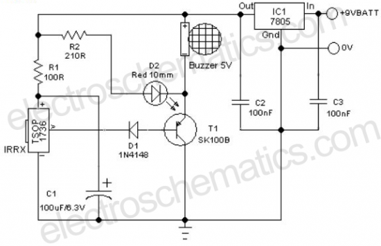
A remote-controlled alarm circuit utilizing the TSOP1736. This circuit involves routing an electric cable to connect a calling bell switch near the bed of an elderly individual. The remote-controlled alarm circuit designed with the TSOP1736 is an innovative solution for...
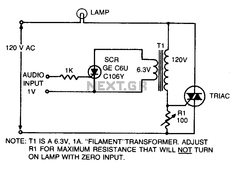
This is an on-off control with an isolated, low voltage input. The switching action occurs rapidly compared to the response time of the lamp and the human eye, resulting in an effect with audio input that resembles a proportional...
The circuit presented this month is a basic configuration of the very versatile 4017 IC Chip. In the most common use of the IC, it will turn on 10 separate outputs sequentially. Typically, the circuit is used to turn...
This project originated from the need for a Li-ion charging circuit that offers more flexibility than typical do-it-yourself circuits while being more affordable than programmable computerized chargers. The primary objective was to design, build, test, and share a charger...
This project is also an essential part of the expandable analyser to be published soon or perhaps eventually, and one meter circuit is used for each frequency band. There are many other uses for a simple LED VU meter....

This is a simple, precise voltage-controlled current source. Bipolar supplies will allow for bipolar output. Configurations that include a grounded voltage-control source and a grounded load tend to be more complex and rely on several components for stability. In...