
Led Expanded Scale Voltmeter Circuit

The circuit employs an A10-V zener diode to achieve a voltage scaling function, enabling a standard voltmeter to measure higher voltage levels. The zener diode operates in reverse bias and maintains a stable output voltage, which in this case is set to 10 V. By connecting the zener diode in parallel with the input voltage, any voltage above 10 V will be effectively clamped, allowing the voltmeter to read from 0 to 5 V based on the scaled input.
The LED bar graph is designed to visually represent the voltage levels above 10 V. It consists of multiple segments, each corresponding to a 0.5 V increment. As the input voltage increases, the bar graph activates one LED segment for every 0.5 V increase, providing a clear and immediate visual indication of the voltage level.
The 7805 voltage regulator integrated circuit is a crucial component in this design, providing a stable 5 V output. This output serves two purposes: it acts as a reference voltage for the measurement circuit and powers the LED segments of the bar graph. The 7805 ensures that the bar graph operates reliably, maintaining consistent brightness regardless of variations in input voltage or load conditions.
In summary, this circuit effectively expands the measurement capabilities of a standard voltmeter using an A10-V zener diode for voltage scaling, an LED bar graph for visual representation, and a 7805 IC for reliable power supply and reference voltage. A10-V zener diode is used to expand the scale of a 0- to 5-V voltmeter to a 10- to 15-V voltmeter. The LED bar graph lights one segment per 0.5-V input above 10 V. The 7805 IC provides a 5-V reference and 5 V for the bar graph LEDs.
Related Circuits
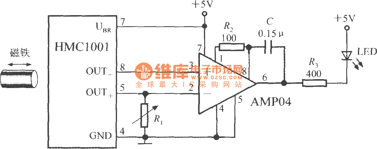
The proximity switch circuit consists of the HMC1001 sensor, operational amplifier (AMP04), and a light-emitting diode (LED). The operational amplifier functions as a comparator. When a magnet, measuring between 6mm and 12mm, is moved to a predetermined position near...

The CD4013 is a dual D flip-flop that operates on the rising edge of the clock signal. Its internal block diagram and pin configuration are provided. This device is part of the standard model C043 and the GB model...

A simple touch dimmer circuit diagram using the TT6061 IC, which is a touch control integrated circuit used for light dimmer circuits and lamp dimmer circuits. The touch dimmer circuit utilizing the TT6061 IC is designed to provide a user-friendly...

None of this triggering circuitry is exactly what is desired, but it will provide a starting point in the right direction. The triggering circuitry mentioned serves as a foundational element for various electronic applications, particularly in the realm of signal...
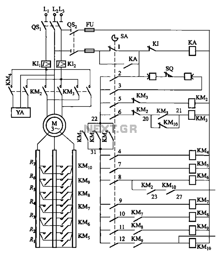
The system is managed by the master controller LKl-12/90 and a magnetic disk control unit PQR10A, which includes a control circuit. The cam control device SA is responsible for contact closure, as indicated in Table 8-5. The main electrical...
This is a silicon transistor circuit showing typical voltage values. When the forward base/emitter voltage is 0.6 to 0.7 V, the transistor is silicon. Germanium transistors will have a forward base/emitter bias voltage of 0.2 to 0.3 V. This...