
LED or Lamp Pulser

The described circuit utilizes a triangular wave generator to control the pulsing of an LED, creating a visually appealing effect as the LED transitions from off to full brightness and back. The core of the circuit is an integrated circuit (IC) featuring two operational amplifiers (op-amps) configured to generate a triangular waveform. This waveform is essential for the gradual increase and decrease in the LED's brightness.
The first op-amp is configured as a non-inverting integrator, which converts a square wave signal into a triangular waveform. The second op-amp operates as a comparator, switching the output state based on the triangular waveform's voltage level. This configuration allows the LED to receive a PWM (Pulse Width Modulation) signal that modulates its brightness according to the triangular wave's amplitude.
Q1 acts as a buffer transistor, providing the necessary current amplification to drive the LED effectively. This buffering ensures that the LED can operate at higher currents without exceeding the output current limits of the op-amps. Proper selection of Q1 is crucial for achieving the desired brightness and response time.
The timing components, R4 (a resistor) and C1 (a capacitor), are critical in determining the frequency and duty cycle of the triangular wave. The values of R4 and C1 dictate the time constant of the circuit, which in this case results in a total period of approximately 4 seconds for a complete cycle of fading in and out. Adjusting these component values will allow for customization of the pulsing speed, enabling variations in the visual effect produced by the LED.
This circuit is suitable for various applications, including decorative lighting, visual indicators, and other scenarios where a dynamic light effect is desired. The simplicity of the design, combined with the low cost of components, makes it an attractive option for hobbyists and professionals alike.This circuit operates a LED in pulsing mode, i.e. the LED goes from off state, lights up gradually, then dims gradually, etc. This operation mode is obtained by a triangular wave generator formed by two op-amps contained in a very cheap 8 pin DIL case IC. Q1 ensures current buffering, in order to obtain a better load drive. R4 & C1 are the timing components: using the values shown in the parts list, the total period is about 4 seconds.
🔗 External reference
Related Circuits
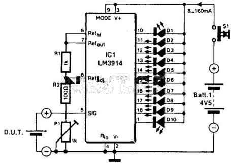
The LM3914A bar graph LED is utilized as a voltmeter for testing batteries. This circuit operates on a 4.5-V battery and compares the battery under test with an internally generated reference, established by resistors R1, R2, and potentiometer P1....
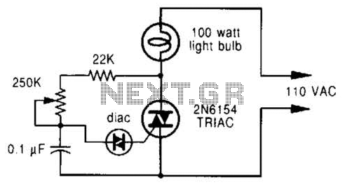
A phase-controlled dimmer delays the triac turn-on to a selected point in each successive AC half cycle. This circuit is suitable only for incandescent lamps, heaters, soldering irons, or universal motors that have brushes. A phase-controlled dimmer is an electronic...
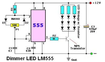
The LM555 timer IC can be utilized in various electronic projects, including the creation of an analog timer. According to the datasheet, the LM555 is versatile and can be adjusted to set timers based on specific requirements. The schematic...
The circuit within the dotted line for a mini emergency light can be integrated into any battery eliminator, provided the eliminator's voltage exceeds that of the battery. For increased load capacity (i.e., for greater illumination through a larger lamp),...
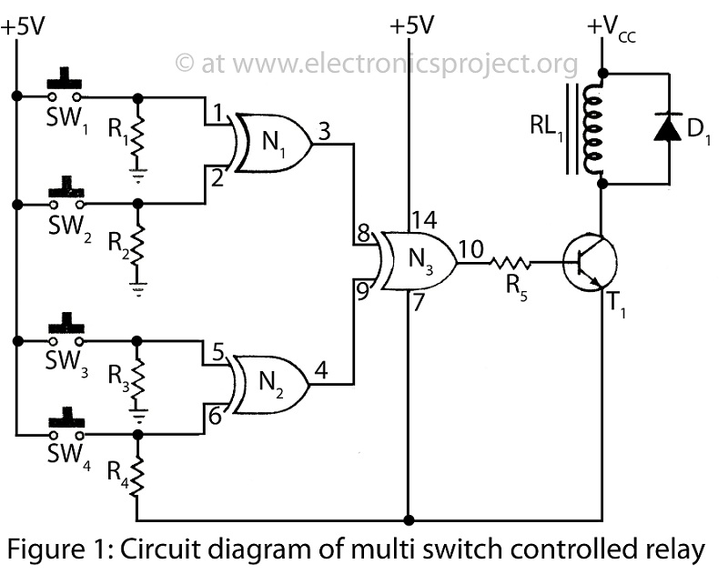
A Multi Switch Controlled Relay circuit is utilized to manage home appliances, featuring a circuit diagram that outlines the application of a multi switch-controlled relay using a single integrated circuit (IC) for various control functions. The Multi Switch Controlled Relay...
A good way to mount the circuit board is to use a hot glue gun to mold the circuit underneath the lamp housing. There is plenty of space there for your board. At the next photos you can see...