
LED output from SB Live! Value
The supply voltage of +5 V is sourced from the USB connector on the computer, allowing the entire converter to be portable and removable while serving as an extension for the relatively short optical cable to the MiniDisc. The trimmer on the converter was adjusted to one extreme position until the LED illuminated, then turned back until the LED turned off. After this setup, the converter input was connected to the yellow jack of the sound card. Following the software switch in the Creative Mixer to output Digital Only, the LED lit up. The optical cable was then connected to the MiniDisc, which was switched on, and the Digital IN REC was pressed. The display indicated DA, and upon playing a music file on the PC, clear sound was produced, having been converted through a single D/A converter in the MiniDisc.Many modern audio recorders is now compatible with digital input S / PDIF (Sony / Philips Digital Interface). Devices like CD Changers, MiniDisc recorders, computer sound cards and the like. working with digital signal just with protocol S / PDIF. Digital connection of two devices, for example. sound card with MiniDisc avoiding D / A converter cards and A / D converter minidisc they bring to the useful signal to noise ratio and cause a linear, harmonic and nonharmonic distortion.
Sound Card SB Live! Value is equipped with a digital output in a yellow 3.5 mm connector labeled DIGITAL OUT. The signal from this jack is activated Software (Creative Mixer) set output to Digital Only. This signal is not compatible with TTL, is adapted for coaxial cable transmission (bipolar signal). Since I needed to connect your sound card with the MiniDisc, which has optical input, so. TOSLINK, I had to check the parameters of the optical signal. Important is the light intensity and wavelength. Optical connectors (eg TOTX from Toshiba fy) are relatively expensive and difficult to hunt. In practice meets vysokosvietivá 5 mm red LED. I also tried the IR diode is useless. Optical cable must be in the axis with the axis of the LEDs and as closely as possible. For these reasons, I made an optical connector with LED on exactly the piece of plastic fiber optic cable connector. Since the LED is at a voltage of about 2.5 V and current needs about 20 mA, I made a very simple digital converter card bipolar signal from the TTL signal, which is driven LED.
Digital signal (conc tip jack) is fed through the input capacitor ode?ovací inverter 7404, to which also brings the bias divider formed trimmer 10k. This bias sensitivity of the entry. Output from the first inverter is connected to the parallel combination of 5 inverters, which together provide sufficient current for LEDs.
The connection can be used conventional integrated circuit with 6 gate MH7404, 74HC04 or CMOS 4069th Supply voltage +5 V I brought from the USB connector on the computer, since I needed to have the whole converter portable, removable, and while I serve as an extension (an optical cable from my relatively short MD). Trimer to the converter I turned to one extreme position where the LED lights up and then I spun it back until the LED goes off.
Only after this setup I connected the converter input into the yellow jack sound card. After the software-switching output (Creative Mixer) for only the Digital LED rozsvietila. I joined minidisc optical cable, switched it on and pressed the Digital IN REC. The display will light up-DA. After running some music file on your PC could be heard clear sound - converted only 1-time D / A converter minidisc. 🔗 External reference
Related Circuits
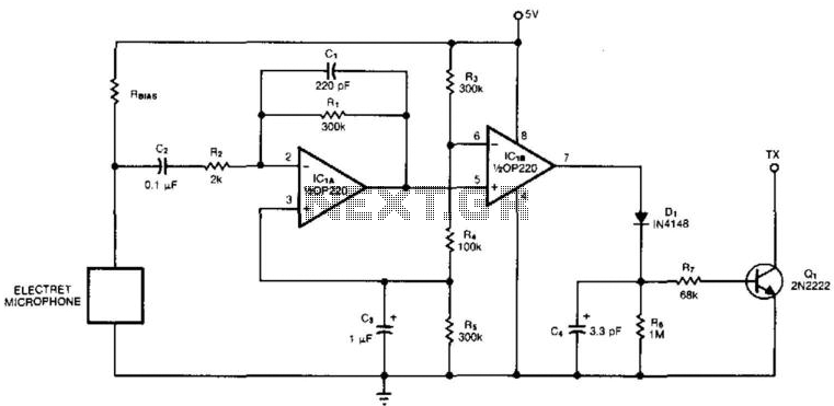
An electret microphone feeds a bandpass filter circuit (IC1A), which subsequently drives a comparator. This comparator activates Q1, a switch that conducts when audio signals from IC1B cause D1, C4, R6, and R7 to bias it ON. The circuit begins...
Supply voltage: 12 V. Supply current: 10 mA in stand-by, max. 80 mA. Input voltage: min. 20 mV rms. Indication range: 30 dB. LED currents: 7 mA. Ref. voltage of IC2: 5 V More: R1 - trimmer 100 k...
Variable-gain amplifiers (VGAs) can be used in many types of systems, such as radio receivers. In this system, the input signal voltage depends on an. Variable-gain amplifiers (VGAs) are integral components in various electronic systems, particularly in radio receivers where...

The major disadvantages of usual linear power supplies are high power dissipation, the size and the appropriated weight. When looking for an alternative solution, I decided to use a switch mode power supply (SMPS). The efficiency of such power...
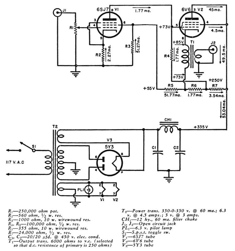
A Direct-Coupled 6V6 Tube Amplifier with Cathode Follower by Raymond H. Bates from Radio & Television News magazine, November 1949. The Direct-Coupled 6V6 Tube Amplifier is designed to utilize a 6V6 vacuum tube, which is known for its warm sound...
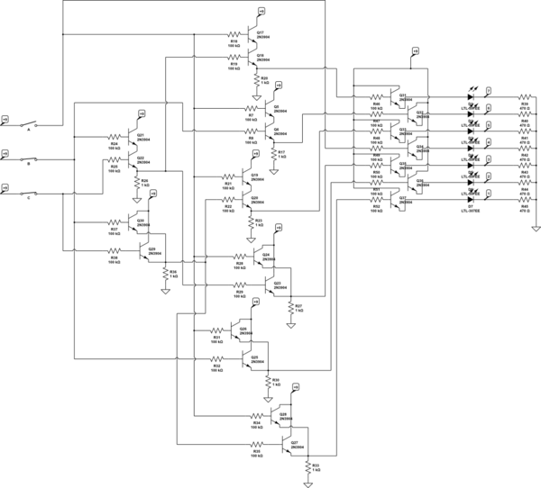
There are three switches that represent a binary number, and according to the combination of those switches, the number of lit LEDs changes to represent that binary number. There is a question regarding how to provide equal current and...