
Light Alarm (Sun Up Alarm)
")
The IC 555 timer is a versatile component widely used in various applications, including timing, pulse generation, and oscillator circuits. In this specific configuration, the IC 555 is employed in astable mode to create a light-sensitive alarm system. The circuit typically comprises a light-dependent resistor (LDR), which detects ambient light levels, and a potentiometer for adjusting sensitivity.
When the ambient light level rises at dawn, the resistance of the LDR decreases, triggering the IC 555 to activate the alarm. The output from the IC can be connected to a piezo buzzer or a speaker, generating a loud sound to wake the user. The alarm duration can be adjusted by modifying the resistor and capacitor values in the timing network of the IC.
To enhance the functionality of the circuit, additional features can be integrated, such as a snooze button, which allows the user to temporarily silence the alarm. Furthermore, an LED indicator can be included to visually signal when the alarm is active. The circuit can be powered by a standard battery or a DC power supply, making it suitable for various applications.
In summary, the IC 555 Light Alarm circuit is an effective solution for individuals requiring assistance in waking up at dawn, with the potential for customization to meet specific user preferences.IC 555, Light Alarm (Sun Up Alarm) , This circuit designed to sound a loud alarm at the break of the dawn especially for those wh cannot wake up even with an alarm clock. Circuit can be modifi. 🔗 External reference
Related Circuits
The terminal of R7, indicated by an arrow, must be connected to the desired output pin of IC2 or IC3 to select the number of LEDs or clusters that will form the bar. For instance, to drive seven LEDs...
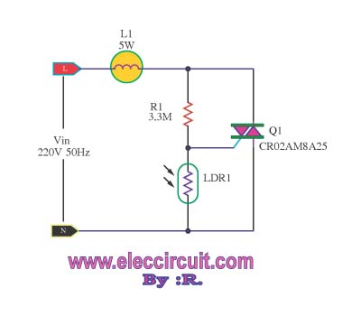
This is an automatic light dimmer circuit. There is no need to manually adjust the brightness of the lights. This circuit is highly convenient, as it utilizes a light-dependent resistor (LDR) to detect external light levels. The automatic light dimmer...
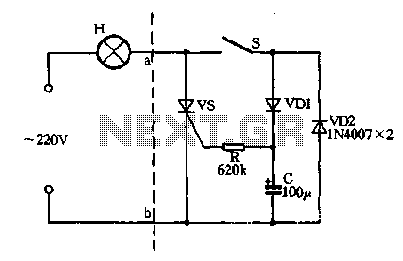
Closing the switch S allows the AC positive half-cycle to flow through diode VDI and resistor R, causing the SCR to open simultaneously at both ends of the capacitor C, which becomes fully charged. During this phase, the positive...
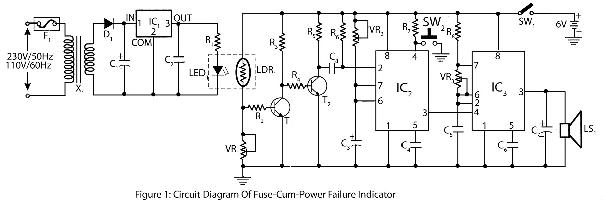
The Fuse Cum Power Failure Indicator utilizes a thermistor and a timer IC (NE555) in its circuit design. The circuit diagram includes a parts list for the fuse cum power failure indicator, which signals instances of power failure. The Fuse...
Auto repair questions concerning brake light issues for the Jeep Grand Cherokee. The Jeep Grand Cherokee features a complex electrical system that integrates various components responsible for the operation of the brake lights. When troubleshooting brake light problems, it is...
All components have been placed on the PCB, but there is uncertainty regarding the connection of the power and load in relation to the relays. The integration of relays into a printed circuit board (PCB) design requires a clear understanding...