
Lie Detector Circut Diagram

The Lie Detector Circuit operates on the principle of galvanic skin response (GSR), which measures the electrical resistance of the skin. When a person becomes anxious or stressed, their skin resistance decreases due to increased perspiration and changes in sweat gland activity. This circuit typically employs a simple resistive divider configuration, where the skin resistance is one of the resistors in the divider.
The circuit often includes components such as an operational amplifier (op-amp) to amplify the small voltage changes resulting from the resistance variations. A microcontroller or a comparator may be used to process the amplified signal and provide a digital output indicating whether the subject is likely to be lying based on the detected skin resistance.
The power supply for the circuit is usually low voltage, often from batteries, to ensure safety during operation. Additional components might include a display unit to visualize the output, such as an LED or an LCD screen, which indicates the results of the lie detection test. Calibration is essential for accurate readings, requiring the circuit to be adjusted based on the individual’s baseline skin resistance under normal conditions.
For practical implementation, the electrodes used for measuring skin resistance should be non-invasive and comfortable for the subject. The circuit can be housed in a portable casing to allow for easy use in various environments. Overall, this Lie Detector Circuit serves as an interesting application of basic electronic principles to explore human psychological responses.This following circuit shows a Lie Detector Circuit Diagram. This circuit is based on the fact that a person`s skin resistance changes when they .. 🔗 External reference
Related Circuits
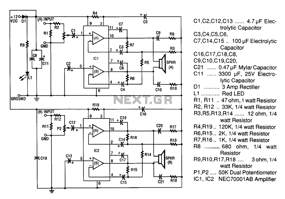
A 20W + 20W stereo amplifier comprises two independent 20-watt RMS amplifiers configured in a bridge arrangement. The input source is connected to a shunt voltage amplifier through resistors R1, R2, and potentiometer P1. Resistor R1 provides load resistance...

This circuit utilizes two quad op-amps to create an eight LED audio level meter. The op-amp employed in this circuit is the LM324, a widely used integrated circuit that is readily available from numerous electronic component suppliers. The 1K...

This circuit utilizes a comparator configured as a Schmitt trigger (311H) along with two active bandpass filters (LM318H) to achieve a 3-kHz output. Higher odd harmonics can be generated by adjusting the active filters to the desired frequency, such...

A simple musical light chaser circuit diagram and schematic using IC CD4016. This circuit blinks lights in response to sound, audio, or music output, causing 10 lights to dance according to sound frequency. The musical light chaser circuit utilizing the...
This project is offered totally free for those who are interested in it. I have tried to make this article as complete as possible, but I will not assume any liability for any errors or omissions in this article....
The circuit depicted is designed to protect a system from power supplies that may exceed safe limits. An example of this is small consumer products that utilize external AC adapters, where there is a risk of accidentally connecting the...