
6 digit LED driver circuit
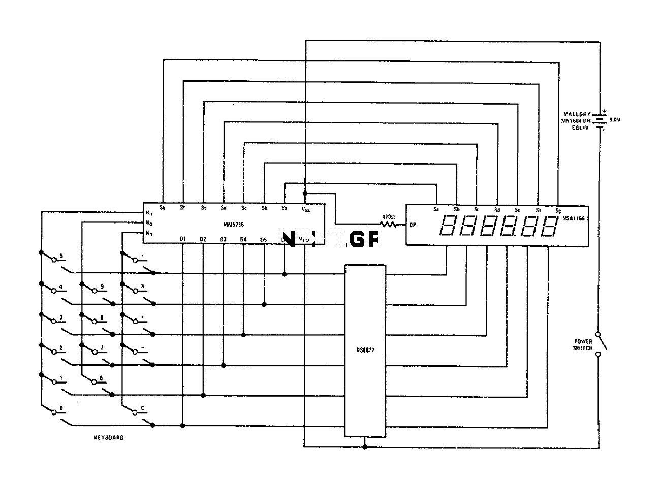
The DS8877 is a versatile driver integrated circuit designed for applications requiring control of display elements, such as in calculators. The circuit configuration involves connecting the DS8877 to a 6-digit display, allowing for the management of current flow between 5 mA and 50 mA, which is suitable for driving LED or LCD segments efficiently.
In this configuration, the DS8877 operates without the need for standby power, which enhances the overall efficiency of the system, particularly in battery-operated devices. The choice of operating voltage is flexible, accommodating 4.5V, 6V, or 9V sources, making the circuit adaptable to various power supply conditions. This flexibility is crucial for ensuring compatibility with different power sources and for optimizing performance across a range of applications.
The circuit design should incorporate appropriate resistors to limit the current to the display elements, ensuring that the current remains within the specified range. Additionally, decoupling capacitors may be included near the power supply pins of the DS8877 to stabilize the voltage and minimize noise, which is essential for maintaining the integrity of the displayed data.
In summary, the DS8877 drive circuit configuration is an efficient solution for controlling a 6-digit display in a compact form factor, with the flexibility of operating voltage and current range, making it suitable for a wide array of electronic devices.Configure National Semiconductors DS8877 drive circuit as shown, when the 6 digit calculator and digital current conjunction, the current range is 5 to 50mA. Drive does not req uire standby power, the operating voltage may be 4.5V, 6V, may be 9V.
Related Circuits
Each zone uses a normally closed contact. These can be micro switches or standard alarm contacts (usually reed switches). Zone 1 is a timed zone which must be used as the entry and exit point of the building. Zones...
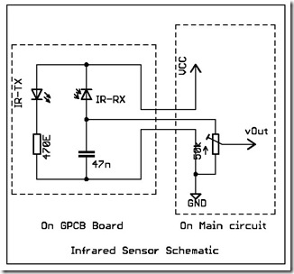
The following circuit illustrates a simple infrared sensor module circuit diagram. Features include a simple infrared sensor module and flame detection. The simple infrared sensor module circuit operates by utilizing an infrared (IR) transmitter and receiver pair. The IR transmitter...
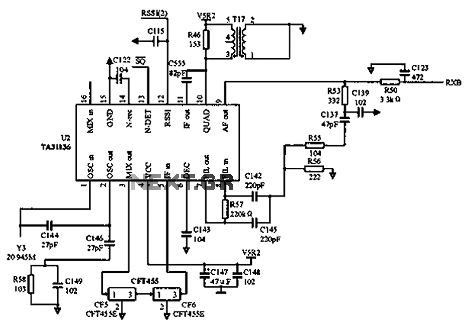
As illustrated in the figure, Vcc is the power supply for the circuit. Upon receiving the initial signal, the frequency is adjusted to 21.7 MHz. This frequency is subsequently enhanced through two crystal filters to improve the selectivity of...
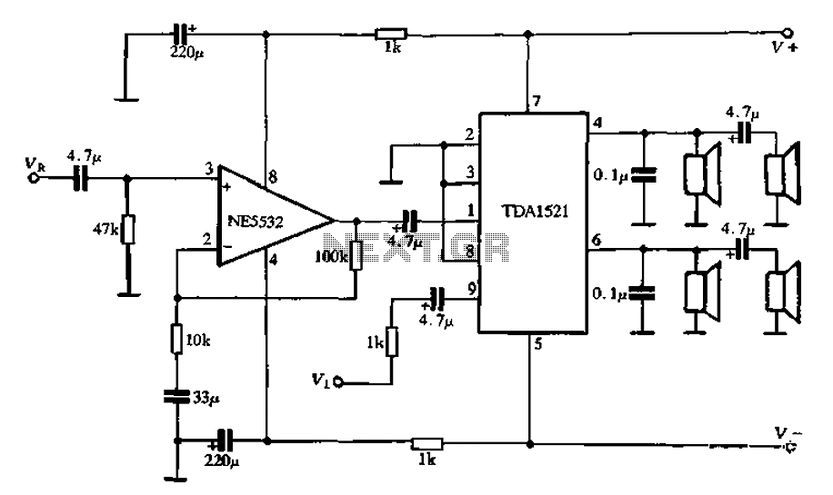
Active speaker with amplifier circuit TDA1521 and NE5532, featuring dual-channel input and dual-channel output. The active speaker circuit utilizes the TDA1521 integrated circuit, which serves as the power amplifier. This IC is designed for high-efficiency amplification, providing a robust output suitable...
The internal disconnection circuit for a blanket operates on the principle of induction. It includes a wire approximately 2 cm in length that senses the proximity of a charged mains power source. When the sensing wire is close to...

The circuit utilizes a 555 timer IC to create a lighting group delay effect, as illustrated in Figure 2-46. It consists of the 555 IC along with a resistor and capacitor configuration that establishes the delay. The circuit remains...