
Car Voltmeter Circuit

The circuit design features a series of ten LEDs arranged to provide a visual representation of the measured voltage level. Each LED illuminates sequentially for each 0.5-volt increment, allowing for an intuitive display of the voltage range. The LM3914 driver is specifically chosen for its ability to drive multiple LEDs in a linear fashion, ensuring accurate representation of voltage levels.
The trimming potentiometer R5 is an essential component, as it allows for calibration of the circuit. By adjusting R5, the voltage reference point can be set to 7.5 volts, which is critical for ensuring that the display accurately reflects the input voltage range. This adjustment helps maintain the linearity of the LED display.
Resistor R7, in conjunction with diode D5, plays a crucial role in regulating the voltage supplied to the LEDs. By ensuring that the voltage does not exceed 3 volts, this configuration protects the LEDs from potential damage due to overvoltage conditions. The use of a low-pass filter, consisting of inductor L1 and capacitor C2, is implemented to smooth out any voltage spikes that may occur in the circuit, thereby enhancing the reliability of the voltage readings displayed.
Furthermore, diode D1 is included in the design as a protective measure against reverse polarity connections. This diode ensures that if the voltmeter is connected in reverse, it will prevent damage to the circuit by blocking any reverse voltage from affecting sensitive components.
Overall, this circuit provides a robust solution for visual voltage monitoring, utilizing a well-thought-out arrangement of components to ensure accuracy, safety, and durability in operation.This screen uses ten LEDs to display a voltage range of 10.5 to 15 volts. Each LED represents a step 0.5wvolt tension. The heart of the circuit is the 3914 points LM / bar display driver. Trimming potentiometer R5 is adjusted so that 7.5 volts is applied to the upper side of the bulkhead. D2 resistor R7 and diode D5 to tighten the voltage applied to the LED 3 volts. A lowpass filter consisting of L1 and C2 guards against voltage spikes. The diode D1 is used to protect against reverse voltage where the voltmeter is connected backwards.
Related Circuits
This circuit allows the use of an inexpensive loudspeaker as a microphone. Sound waves that reach the speaker cone create fluctuations in the voice coil. The movement of the voice coil within the speaker's magnetic field generates a small...
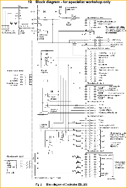
The following circuit illustrates an Elektroblock circuit diagram utilizing a 12V power supply. Features include various control and monitoring functions, with the specification of an 18 A LAS 1218 component. The Elektroblock circuit is designed to operate with a 12V...
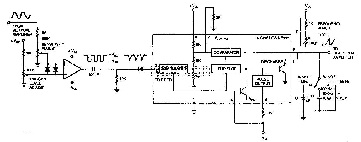
The circuit's input operational amplifier triggers the timer, sets its flip-flop, and cuts off its discharge transistor, allowing capacitor C to charge. When the voltage across the capacitor reaches the timer's control voltage of 0.33 Vee, the flip-flop resets,...

This circuit is based on a simple asymmetric oscillator. The duration for which the relay remains energized and the duration for which it remains de-energized are independently set. With the component values indicated in the diagram, both durations are...
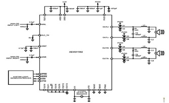
This is a typical stereo application circuit schematic of the ADAU1592, a 2-channel, bridge-tied load (BTL) switching audio power amplifier. The ADAU1592 can be utilized in flat panel televisions, PC audio systems, and mini-component applications. The ADAU1592 is designed to...

Voltage variations and power cuts adversely affect various equipment such as TVs, VCRs, music systems, and refrigerators. This simple circuit will protect costly equipment from high and low voltages and voltage surges when power resumes. It also produces a...