
Lamp Dimmer schematic
The circuit operates as a phase control dimmer for AC loads, utilizing a full-wave rectification approach to manage power delivery. The four diodes are arranged in a bridge configuration, ensuring that regardless of the AC polarity, the load receives a rectified voltage, which is critical for the SCR's operation. The SCR (Silicon Controlled Rectifier) serves as a controlled switch that allows current to flow through the load once it is triggered by the gate signal.
The timing mechanism is pivotal for controlling the phase angle at which the SCR is turned on. The capacitor (2.2 µF) charges through the 50K potentiometer, and once the voltage across it reaches approximately 8 volts, the small signal transistors switch on. This action discharges the capacitor into the gate of the SCR, turning it on and allowing current to flow through the load for the remainder of the AC cycle.
The adjustment of the 50K potentiometer directly influences the charge time of the capacitor. A lower resistance allows the capacitor to charge faster, thereby triggering the SCR earlier in the AC cycle, which increases the average voltage applied to the load. Conversely, increasing the resistance delays the SCR's triggering, resulting in a lower average voltage across the load.
Furthermore, the 15K resistor serves as a calibration tool, allowing for fine-tuning of the output voltage when the 50K potentiometer is set to its maximum. This feature is essential for ensuring the circuit can accommodate variations in component tolerances, enabling the user to achieve the desired performance without compromising safety or functionality.
It is critical to observe safety precautions when working with AC circuits, as they can pose significant electrical hazards. Proper insulation and handling practices must be followed to prevent accidental contact with live components.The full wave phase control circuit below was found in a RCA power circuits book from 1969. The load is placed in series with the AC line and the four diodes provide a full wave rectified voltage to the anode of a SCR. Two small signal transistors are connected in a switch configuration so that when the voltage on the 2.2uF capacitor reaches about 8 volts, the transistors will switch on and discharge the capacitor through the SCR gate causing it to begin conducting.
The time delay from the beginning of each half cycle to the point where the SCR switches on is controlled by the 50K resistor which adjusts the time required for the 2uF capacitor to charge to 8 volts. As the resistance is reduced, the time is reduced and the SCR will conduct earlier during each half cycle which applies a greater average voltage across the load. With the resistance set to minimum the SCR will trigger when the voltage rises to about 40 volts or 15 degrees into the cycle.
To compensate for component tollerances, the 15K resistor can be adjusted slightly so that the output voltage is near zero when the 50K pot is set to maximum. Increasing the 15K resistor will reduce the setting of the 50K pot for minimum output and visa versa.
Be careful not to touch the circuit while it is connected to the AC line. 🔗 External reference
Related Circuits
This wide-range light dimmer circuit utilizes a unijunction transistor and a pulse transformer to implement phase control for the TRIAC. It operates from a 115-volt, 60 Hz source and is capable of controlling up to 800 watts of power...
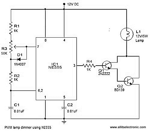
A simple and efficient PWM lamp dimmer utilizing the timer IC NE555 is presented in this article. Traditional linear regulator-based dimmers achieve a maximum efficiency of only 50%, which is significantly lower than PWM-based dimmers that can exceed 90%...
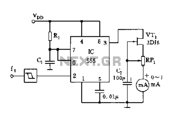
The circuit consists of a 555 timer along with components R1, C1, and other elements configured as a monostable delay circuit. The input square wave signal is shaped by a Schmitt trigger to meet the triggering requirements. The 555 timer...
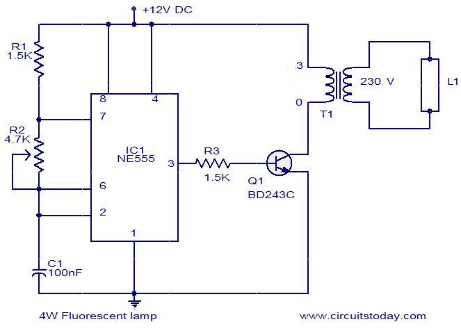
This is a simple 4W fluorescent lamp driver circuit that can be operated from a 12V supply. The first part of the circuit includes a NE555 timer IC configured as an astable multivibrator. The output pulses from the IC...
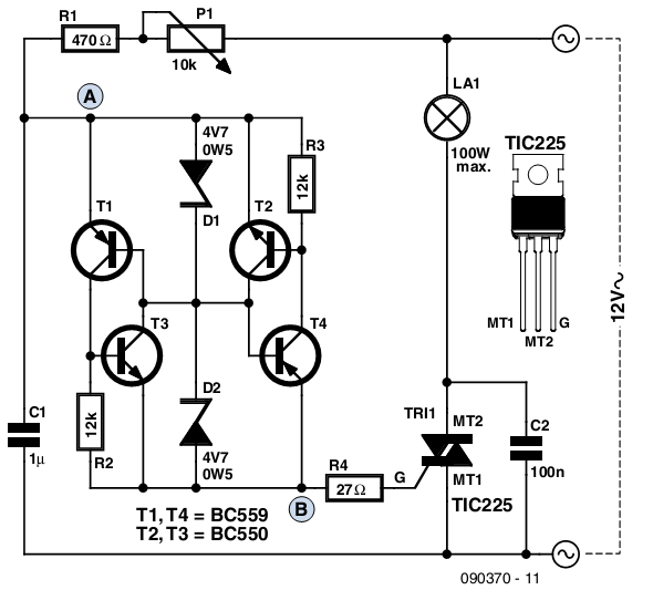
The circuit presented is based on a conventional design for a simple lamp dimmer, featuring a diac connected between points A and B. Unlike standard diac circuits that require a trigger voltage of 30 to 40V, this design operates...
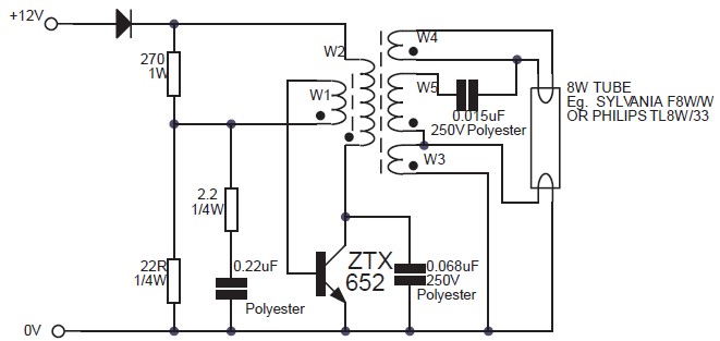
This circuit is an 8W inverter designed to drive an 8W fluorescent lamp from a 12V power supply, utilizing an inexpensive inverter based on a ZTX652 transistor. The inverter operates from power supplies ranging from 10V to 16.5V, achieving...