
Lightning Detector Circuit

The DIY lightning detector circuit utilizes a simple yet effective design to detect electrical discharges associated with thunderstorms. The circuit operates primarily through a feedback oscillator that is finely tuned to respond to the weak electric fields generated by lightning activity. The aerial, which acts as an antenna, captures these fields and channels them into the circuit.
The heart of the circuit consists of two transistors (TR1 and TR2) configured to amplify the signal detected by the aerial. The feedback loop between the two transistors ensures that the circuit remains in a state of oscillation, which is crucial for detecting the rapid changes in voltage that occur during a lightning discharge. The adjustment of the multiturn preset resistor (VR1) allows for precise control over the sensitivity of the detector. This is critical, as the circuit must be able to differentiate between normal background static and the significant pulses produced by lightning.
The circuit's output can be tailored to provide both audible and visual alerts. The piezo buzzer emits a sound when a discharge is detected, while an LED can be configured to flash, providing a clear visual indication of storm activity. The design allows for flexibility in the choice of output devices, provided they meet the minimum voltage and current specifications.
In terms of power consumption, the circuit is designed to be energy-efficient, drawing only 600 µA in standby mode, which is suitable for prolonged outdoor use. The choice of a 9-volt battery ensures that the circuit has sufficient power for operation, even under continuous monitoring conditions.
Regarding the substitution of the BC109 transistor with a BC517 Darlington transistor, it is important to note that the BC517 has a higher current gain, which may affect the overall sensitivity and response time of the circuit. If using the BC517, adjustments may need to be made to the biasing resistors to accommodate the different characteristics of the transistor. Additionally, the feedback configuration may require recalibration to ensure proper oscillation and sensitivity.
To enhance the detection range for mobile phones, one approach could be to increase the size of the aerial or use a more sensitive receiving circuit. This may involve experimenting with different antenna designs or incorporating additional amplification stages to boost the signal captured from mobile devices. Further research into mobile phone detection technologies may provide additional insights into effective methods for improving detection capabilities.This DIY lightning detector circuit is a very sensitive static electricity detector that can provide an early warning of approaching storms from inter-cloud discharge well before an earth-to-sky return strike takes place. An aerial (antenna) formed of a short length of wire detects storms within a two mile radius. The circuit emits an audible warn ing tone from a piezo buzzer, or flashes an LED for each discharge detected, giving you advance warning of impendig storms so that precautions may be observed. The primary feature in the lighting detector is the circuit`s ability to be set close to self-oscillation, with its relaxation optimised via the bias resistor values shown in the circuit diagram.
The oscillator is dc coupled and feedback is routed through the collector of TR1 to the base of TR2, while the overall loop gain is set with the multiturn(12, 18 or 22) preset VR1. To set up the lightning sensor, adjust preset VR1 for oscillation by monitoring test point TP1, which should be at roughly 7volts peak-to-peak.
Test point TP2 should be at +6V dc. Now readjust VR1 back slightly to stop oscillation; use a screwdriver to touch the aerial-side of C1 several times; the alarm should sound for 1 or 2 seconds then stop. If it continues, make a very small adjustment back and recheck. The other method is to electrostatically charge a plastic ruler and then draw your finger close to discharge, about two meter away from the aerial.
Powered from a 9 volts battery the circuit consumes about 600 µA in standby. Powered continously it could provide a good year of uninterrupted monitoring. When sounding the alarm, the current will rise to 4mA depending on the low current sounder WD1. A minimum 3 volts device is required for a good output level and it will produce a pinging alarm to warn in real time of any electrostatic pulse activity. the bc109 transistor aint selling at our closest electronics store so can i use the bc517 darlington transistor, and if so what do i need to change in the lightening detector circuit to use that transistor i have tried out the mobile sniffer for my project and it came out well .
but i need some help with this, how can i increase the range of detection of the mobile phones plzzzz help me. 🔗 External reference
Related Circuits

Pressing the pushbutton on the transmitter activates a sound and/or light alert in the receiver. This system operates without wiring or radio frequencies; instead, the transmitted signal is conveyed through the mains supply line. It is suitable for use...

This design schematic represents a Class A power amplifier. It closely matches the operating parameters of Class B to facilitate comparison, particularly with a negative feedback (NFB) factor of 30dB at 20 kHz. The front end is similar to...

The switch circuit consists of a capacitive oscillator, an integration network, and a comparator circuit that controls a relay. When a body comes close to the induction plate, the inductive capacitance to ground increases, causing the 555 astable multivibrator...
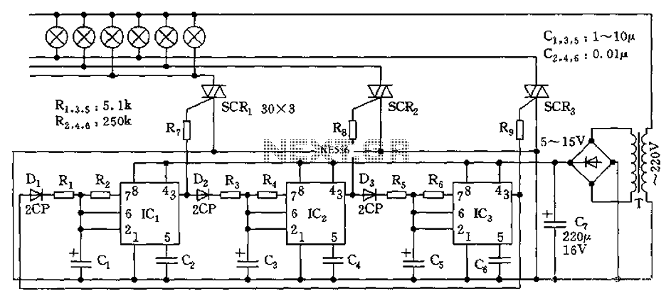
The circuit utilizes a 555 timer as its core component to control three lights through a cyclic trigger monostable delay circuit. The brightest light is controlled by a silicon-controlled rectifier (SCR) that determines the cycle of illumination. When pin...

The SLB0586A integrated circuit from Siemens can be utilized to construct a straightforward touch light dimmer circuit, enabling the adjustment of lamp intensity. When paired with a TIC206D triac, this setup allows for smooth regulation of light intensity for...

The proximity switch using the 555 timer functions as a monostable trigger circuit. The trigger pin (Pin 2) of the 555 timer is connected through a large resistor (R2) to the positive supply voltage (VDD) and is in a...