
Line follower obstacle avoider

The robot's design emphasizes a straightforward construction process, making it accessible for those new to robotics and electronics. The combination of LDRs and LEDs for line detection is a common and effective method in simple robotic applications, providing reliable feedback for navigation. The differential drive mechanism allows for responsive movement and precise control, ensuring that the robot can follow the line accurately. The inclusion of decoupling capacitors serves to enhance the overall performance and reliability of the motors, which is particularly important in low-cost designs where component quality may vary. The use of a potentiometer in the voltage divider circuit allows for fine-tuning of the sensor's sensitivity, enabling the robot to adapt to different lighting conditions and surface colors. Overall, this project serves as an excellent introduction to basic robotic principles, circuit design, and component integration, fostering a greater understanding of electronics and robotics.This tutorial details the construction of a simple and low cost robot. The robot is mainly a line follower but can also be used as a photovore, a photophobe, and obstacle avoider!And all this for less than 40$. The best part is that the robot does not use any microcontroller, which means you need no expensive programmer or even a computer to progr
am your robot. This tutorial is mainly aimed at beginners, hence I have tried to keep the robot as simple and cheap as possible. With only a few parts you can get this robot up and going. Here is a video of the robot following black line. I bought the motor, wheels and L-Bracket from a local store. I`m not sure if you can buy the same parts online. But similar parts are available at hobbyengineering. com For designing the robot chassis I used Google SketchUp, which is a free 3D modelling software. I didn`t include much detail in the model like the electronic components, wires etc. The robot uses differential drive as its steering mechanism. When the sensors sense the black line the corresponding motor is stopped until the sensors are back on the white surface.
Thus, the robot is able to stay on the line. Before building the chassis, you will have to add 0. 22uF decoupling capacitors across the motor terminals. This not only increases the life of the motors but also reduces noise in the circuit. This is an optional step. Make sure that you print the template to size (8cm x 9cm). To print the template to size, save the template in your PC. Once saved, right click on the template and select Edit`. The template should open in Paint, where you have to click on the Print option under the File menu to print the template to scale. This is only for Windows users. Once the holes are drilled, attach the L-Brackets to the base with the help of screws. The L-Brackets will be used to mount the motors to the base. You may also use other materials like clamps and rubber bands instead of L-Brackets if you can`t find the right L-Bracket for your motor.
As I told before, I bought the wheels from a local store. The wheels I used had a diameter of 7. 5 cm. To attach the wheel to the shaft of the motor, I forced the shaft of the motor into the extended shaft of the wheel and tightened the setscrew. As told before, the robot uses a combination of LDRs and LEDs to sense the presence to a line. An LDR is a resistor whose resistance is proportional to the light falling on it- greater the light, lesser the resistance and visa-versa.
The basic principle underlying this project is that objects light in colour radiate the light falling on them while dark coloured objects don`t. So when the sensors are above the black line the light emitted by the LED is not radiated by the floor, hence the resistance of the LDR increases.
The opposite happens when the robot back on the white surface. In our robot the LDR is used part of a voltage divider circuit. To know more about voltage dividers and LDRs visit The circuit diagram of the voltage divider used in this project is given below The resistor whose value is 20K is a potentiometer. A potentiometer (pot or preset) is a resistor whose resistance can be changed. In our project, we will be using 20k presets, that is, we will use presets whose resistance can be changed from 0K to 20K.
When the robot is on white surface the light emitted by the LEDs fall on the LDRs and decreases its resistance. This in turn reduces the voltage at Vout. When the robot is on the black line, the light emitted by the LEDs does not reach the LDRs, hence its resistance increases.
This in turn increases the voltage at Vout. During both the cases it is necessary to adjust the 20K preset in such a way that, when the robot is on white surface, voltage at Vout is <0. 8V (so that the voltage at the emitter of the transistor is LOW) and when the sensor is on the black line the voltage is >0.
8V (so that the voltage at the emitter of the trans 🔗 External reference
Related Circuits
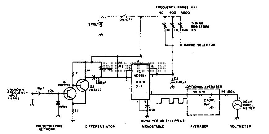
The 555 timer is utilized in a monostable multivibrator circuit that generates a pulse of fixed time width, which is activated by an unknown input frequency. The 555 timer in a monostable configuration operates by producing a single output pulse...
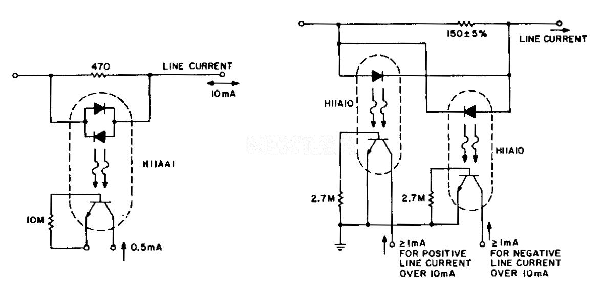
The detection of line-current flow and its indication at an electrically remote point is essential for line status monitoring in various telephone systems and auxiliary systems. The monitoring circuit must minimally unbalance or load the line, while also being...

Most analog multimeters can measure resistance across a wide range of values; however, they can be inconvenient due to their reverse reading scale, which is also non-linear. This can lead to poor accuracy, especially at the high-value end of...
The above diagram is a standard low-pass telephone line filter (L1,C1,L3,C2). L2 and L4 are needed since we're dealing with the 'Tip' and 'Ring' of a phone line which may carry up to 90VAC. Additional info can be found...
It is quite easy to get a watt or more with very simple equipment, but to get more than 5 watts becomes a little more difficult. This article describes a 10 watt linear amplifier that is capable of delivering...
The typical BPM range for music is between 40 and 240 BPM, corresponding to periods of 1500 ms and 200 ms, respectively. A BPM of 120 equates to a period of 500 ms. The circuit requires a resistor R4...