
Line Following Robot

Modifying servomotors involves a systematic approach to disassembly and reconfiguration of the internal components. The initial step is to unscrew the four screws that hold the servo casing together, which typically requires a small Phillips screwdriver. After removing the screws, the servo can be gently pried apart to access the internal mechanism.
Once disassembled, attention should be directed towards the electronic components housed within the servo. It is essential to carefully detach these components while ensuring that the wiring remains intact for future modifications. The wires are crucial as they will connect the modified servo to a control system or microcontroller.
After the electronics have been removed, modifications can be made to enhance the performance of the servomotor. This may include upgrading the motor for better torque or speed, altering the feedback mechanism, or integrating new control circuitry. It is critical to ensure that any modifications align with the intended application of the servomotor, whether it be for robotics, automation, or other applications.
Once modifications are complete, the servo should be reassembled, ensuring that all components fit securely within the casing. The final step involves testing the modified servomotor to verify that it operates as intended and meets the desired specifications. Proper testing will help identify any issues that may arise from the modifications and allow for further adjustments if necessary.How to Mod the Servomotors (look at the pictures) Remove the four screws from the servo and take it all apart. Remove the electronics keeping only the wires from th.. 🔗 External reference
Related Circuits
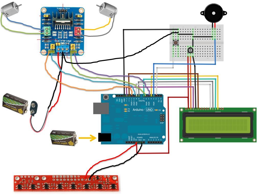
If the robot is positioned on the black line, it will continue moving forward. However, if it veers off the line and enters a white area, it will assess whether to correct its path to the left or right,...
This circuit will allow you to connect any tape recorder that has a mic and remote input to a phone line and automatically record both sides of a conversation whenever the phone is in use. You will need to...
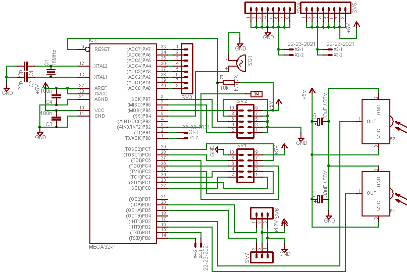
In this project, an ATMEGA16 microcontroller operating at 16MHz will be utilized. To distinguish this project from others, a unique feature has been incorporated: a battery monitoring system. Many robots operate on new or freshly recharged batteries, and if...
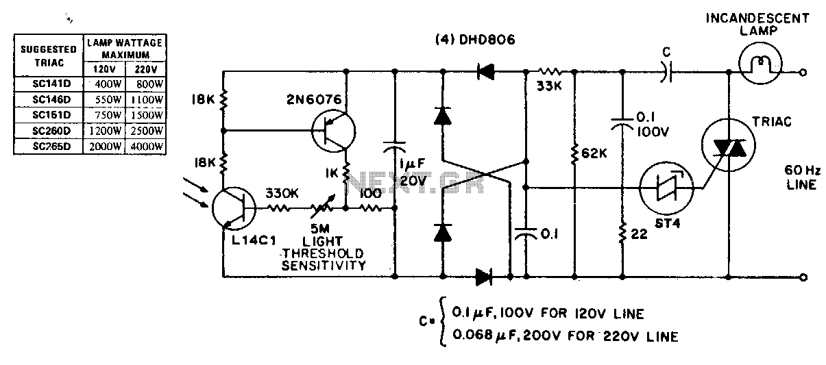
This circuit exhibits stable threshold characteristics based on the photo-diode current in the Ll4Cl, which generates a base-emitter voltage drop across the sensitivity setting resistor. The double phase shift network that supplies voltage to the ST-4 trigger ensures triac...
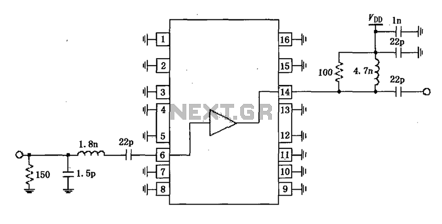
A narrowband linear amplifier circuit configured with the RF2320 operates within a frequency range of 1930 to 1990 MHz. The radio frequency (RF) signal is input from a distance of 6 feet and is amplified by an internal amplifier...
The circuit shown demonstrates how to power one or two LEDs from a 120-volt AC line by utilizing a capacitor to reduce the voltage and a small resistor to limit the inrush current. Because the capacitor needs to conduct...