
LM1889 IC For Simple TV Transmitter

The circuit utilizes the LM1889 IC, which is designed for television applications, particularly for generating the necessary video signals for transmission. The IC integrates various functions required for the modulation of chrominance and luminance signals, enabling the generation of a composite video output suitable for RF transmission.
In this configuration, the input video signal is processed through the LM1889, which modulates the chroma signal using quadrature techniques. This modulation is essential for maintaining the quality of the color signal in the transmitted output. The RF section of the circuit typically includes a power amplifier and an oscillator, which are responsible for converting the modulated video signal into a radio frequency suitable for broadcasting.
The circuit may also include additional components such as resistors, capacitors, and inductors to filter and stabilize the output signal, ensuring that it meets the necessary specifications for transmission. Proper layout and component selection are critical to minimize interference and maximize the range and clarity of the transmitted signal.
Overall, this simple TV transmitter circuit provides a foundational understanding of how video signals can be transmitted over radio frequencies, utilizing the capabilities of the LM1889 IC for effective modulation.The following circuit shows about simple TV Transmitter Circuit Diagram. This circuit based on the LM1889 IC. Features: quadrature chroma modulators and RF .. 🔗 External reference
Related Circuits
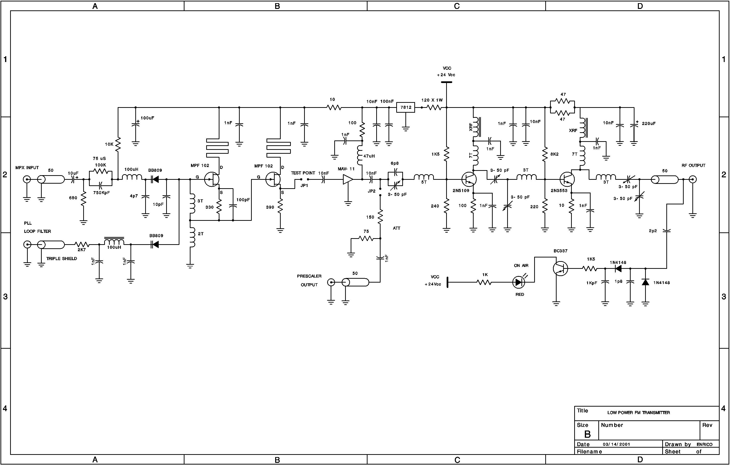
A low power FM pirate radio. The output power is approximately +35 dBm (3.16 watts) over a 50-ohm load and operates on a +24-volt power supply. The project consists of a Hartley oscillator (modulated VCO) and three stages (Class...
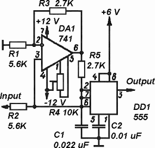
The timer is utilized in a conventional setup, with the exception that the timing resistor has been substituted with a current source derived from the operational amplifier DA1 (741). This modification enables the achievement of excellent linearity, exceeding 3%....
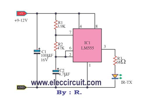
This infrared remote control transmitter circuit exhibits high performance and can be utilized with various infrared receiver circuits. It is designed for ease of construction and cost-effectiveness. Additionally, another circuit is intended for broader applications and requires programming to...
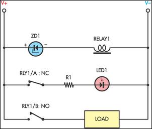
Sensitive low-current relay coils often operate at much lower voltages than their typical ratings. This can be undesirable in some applications, where low supply voltages can result in erratic system behavior. In some instances, this problem could be overcome...
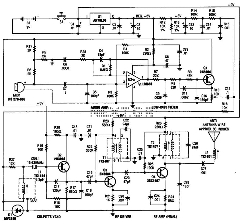
This tracking transmitter consists of four distinct subassemblies: a free-running multivibrator, a transmit switch, an audio-tone generator, and an FM transmitter. The multivibrator, which produces a pulse width with a pulse separation of 1500 ms, is built around Q1...
In electronics, filter circuits are primarily used to restrict the passage of certain frequency ranges while allowing other frequency bands to proceed to subsequent stages of the circuit. A high-pass filter circuit permits only frequencies that exceed a specified...