
LM358 IC Solar Controller

The LM358 IC Solar Controller Circuit utilizes the operational amplifier LM358 to regulate and manage solar energy. This circuit is designed to optimize the charging of batteries, ensuring efficient energy conversion from solar panels. The LM358 consists of two independent, high-gain, frequency-compensated operational amplifiers, making it suitable for various applications, including solar energy management.
In this configuration, the circuit typically includes a solar panel, a battery, and the LM358 IC. The solar panel generates voltage when exposed to sunlight, which is then fed into the non-inverting input of one of the operational amplifiers. The output of this amplifier controls a switching element, such as a MOSFET or a relay, which connects or disconnects the solar panel from the battery based on the battery's charge level.
The second amplifier in the LM358 can be used for voltage comparison, ensuring that the battery does not overcharge by disconnecting the solar panel when the battery reaches a certain voltage threshold. Additional components, such as resistors and capacitors, are included to set the reference voltage levels and to filter any noise that may affect the operation of the circuit.
This solar controller circuit is particularly beneficial for mobile communication base stations, where reliable and efficient power management is crucial. It can also be adapted for various other applications that require solar energy conversion, making it a versatile solution for renewable energy systems.The following circuit shows about LM358 IC Solar Controller Circuit Diagram. Features: also as a mobile communications base stations, convert .. 🔗 External reference
Related Circuits
This circuit is designed to charge NiCd or NiMH batteries using solar cells. It maximizes power extraction from a solar array to charge a battery stack. The circuit utilizes the MAX856 boost converter and the MAX982 dual comparator with...
This circuit is an automatic street light controller. The sensor used to detect changes in light is an LDR (Light Dependent Resistor). The working principle of the LDR is that when exposed to light, its resistance value decreases, while...
This DC drill speed controller circuit allows for the adjustment of the rotational speed of a drilling machine. A mini-drill machine is always... This circuit utilizes a pulse-width modulation (PWM) technique to control the speed of a DC motor, which...
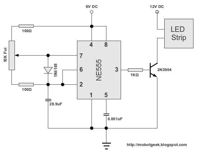
After restoring its engine and other mechanical components to optimal condition, the next step involved adding aesthetic lighting. A visit to a local electronics store resulted in the discovery of 12V DC-operated LED strips, which were ideal for the...
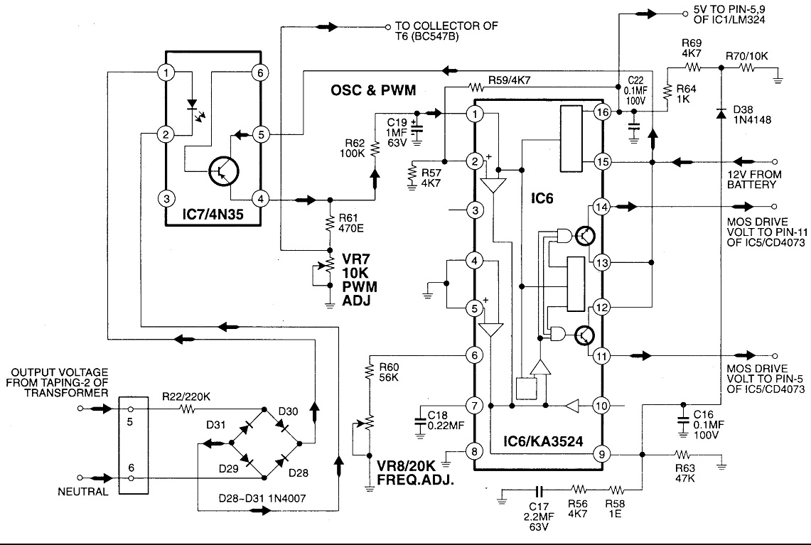
Circuit No. 1 (Oscillator Circuit and Feedback Circuit) Circuit No. 2 (MOS Driver Circuit) Final Product: - Operation of Circuit No. 1 (Oscillator Circuit and Feedback Circuit) This inverter utilizes Pulse Width Modulation (PWM) technology. The working principle of...
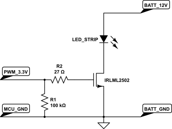
A strip of LEDs is controlled by a microcontroller using pulse-width modulation (PWM) to adjust brightness. The LED strip requires approximately 1.5A at 12V. The user, who has experience only with low-power digital electronics, seeks confirmation of their assumptions...