
Visual modulation indicator

Cl = 5 pF, C2 = 100 pF, Dl = 1N60 or 1N34 (Germanium), R3 - 10 K pot, II = 6-8 V, 30-60 mA incandescent bulb, Q1 = 2N3393 (for increased sensitivity, use 2N3392 or another high-gain transistor).
The described circuit utilizes an indicator lamp to visually represent the amplitude of a modulated RF signal. The primary component responsible for this functionality is the variable resistor R2, which allows for fine-tuning the sensitivity of the lamp's response to the modulation. When the transmitter is activated, the RF signal modulates the current flowing through the circuit, causing the lamp to illuminate in a manner that corresponds to the modulation pattern.
The circuit includes a capacitor (Cl) of 5 picofarads and a second capacitor (C2) of 100 picofarads. These capacitors serve to filter and stabilize the signal, ensuring that the variations in brightness are smooth and accurately reflect the modulation. The diode (Dl), either a 1N60 or 1N34 Germanium type, is essential for rectifying the RF signal, allowing only the positive half-cycles to pass through, which is crucial for the operation of the indicator lamp.
Resistor R3, a 10 K potentiometer, provides an adjustable load that can be tuned to optimize the performance of the circuit. The power supply voltage (II) is specified to be between 6 to 8 volts, which is suitable for driving a 30-60 mA incandescent bulb. The choice of the 2N3393 transistor as Q1 is important for amplifying the signal; however, for applications requiring increased sensitivity, a 2N3392 or another high-gain transistor may be substituted.
Overall, this circuit effectively demonstrates how an indicator lamp can be utilized to visualize the characteristics of an RF signal modulation, providing a practical application for testing and tuning RF transmission systems.Indicator lamp brightness varies in step with modulated RF signal. Adjust R2 with transmitter on (modulated) until the lamp flashes in step with modulation Cl = 5 pf, C2 = 100 pF, Dl = 1N60 or 1N34 (Germanium), R3 - 10 K pot, II = 6-8 V, 30-60 mA incandescent bulb, Q1 = 2N3393 (for increased sensitivity use 2N3392 or other high-gain transistor).
Related Circuits
The circuit indicates two different water temperature trip points by activating LEDs when the specified temperatures are reached. It is built around the LM2904 dual operational amplifier, which is powered by a 12 V automotive system. A thermistor is...
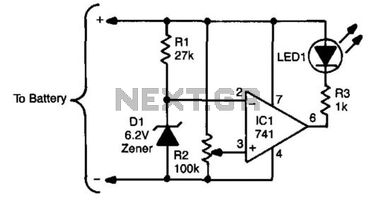
The sensing circuit consists of a 741 op-amp configured as a voltage comparator, utilizing a zener diode as a voltage reference. The op-amp is positioned as a bridge between two resistor ladders; one includes the zener reference, while the...

The ISL8107 is a single-phase, non-synchronous buck controller equipped with an integrated high-side MOSFET driver. It operates within an input voltage range of 9V to 75V. The internal reference voltage is 1.192V with a tolerance of ±1% across the...
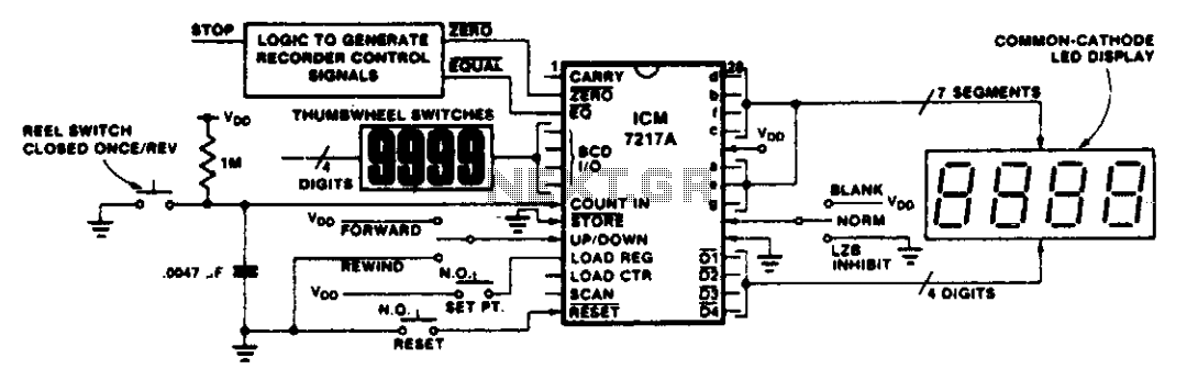
This circuit illustrates various applications of up/down counting for monitoring dimensional position. In the tape recorder application, the LOAD REGISTER, EQUAL, and ZERO outputs are utilized to control the recorder. To ensure the recorder stops at a specific point...

Light-emitting diodes connected with reverse polarity provide a visual indication of zero-beat frequency. Each LED is on for only half a cycle of the input. When the input frequency is more than 1 kilohertz away from the zero-beat frequency,...
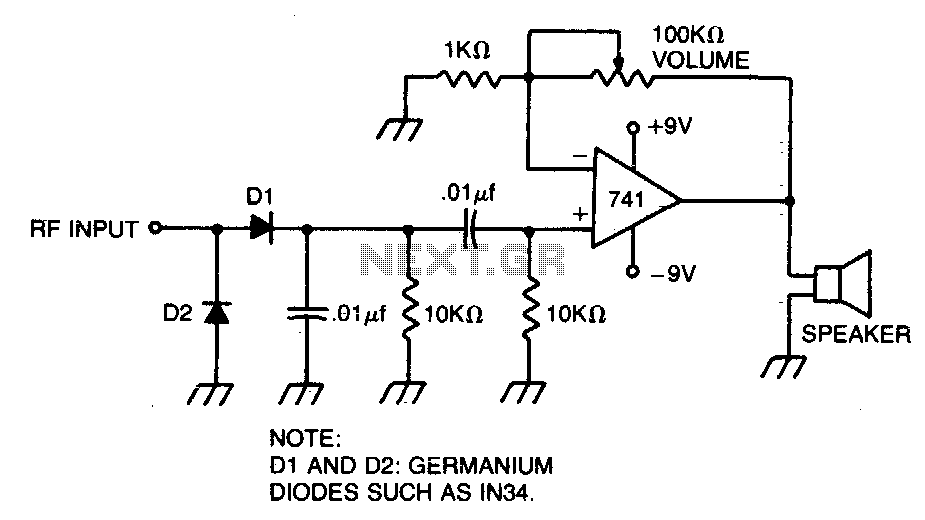
A broad-tuned receiver demodulates the RF signal picked up by a loosely coupled wire placed near the transmitting antenna. The broad-tuned receiver operates by utilizing a loosely coupled wire antenna, which is strategically positioned in proximity to the transmitting antenna....