
Low Cost Amplifier Circuit Using Three Transistors

The low-cost amplifier circuit employs two types of transistors, BC107 and BC148, which are commonly used for their favorable characteristics in audio amplification applications. The BC107 is a general-purpose NPN transistor, while the BC148 is also an NPN transistor with slightly higher voltage ratings, making them suitable for various amplification tasks.
The circuit typically consists of a common-emitter configuration, where the input signal is applied to the base of the first transistor (BC107). This transistor amplifies the input signal, and the output is taken from its collector. The amplified signal is then fed into the base of the second transistor (BC148), which further amplifies the signal. The output from the collector of the BC148 provides a higher power version of the input signal.
Biasing resistors are essential in this circuit to ensure that both transistors operate in the active region. The resistors set the base current, allowing for proper operation without distortion. Capacitors may also be included to couple the input and output signals while blocking any DC components, ensuring that only the AC signal is amplified.
The power supply for the circuit typically ranges from 9V to 12V, which is adequate for the operation of both transistors. A bypass capacitor may also be used across the emitter resistor to enhance the gain at higher frequencies.
This low-cost amplifier circuit is particularly beneficial for applications where budget constraints exist, yet reliable audio amplification is required. The simplicity of the design, along with the availability of the components, makes it an excellent choice for hobbyists and educational purposes in electronics.The working and circuit diagram of a low cost amplifier using transistors BC107, and BC148 is explained in detail.. 🔗 External reference
Related Circuits
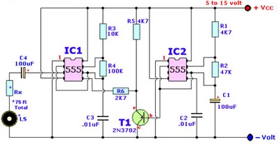
Browse home alarm circuit explanation latest schematic siren wailing with latest Wailing Alarm Siren circuit schematic with explanation. The loudspeaker LS and the resistor marked Rx should be together 75 ohms. If a standard 8-ohm speaker is used, then...
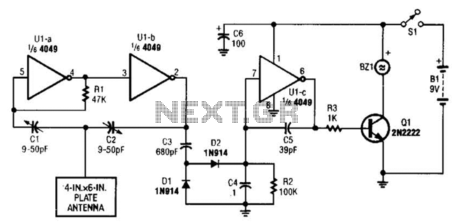
A CMOS logic gate is utilized in this circuit. When an object approaches the antenna, the change in oscillator output is detected by components 1)1 and 1)2, which is then amplified by U1C. This amplification drives Q1, activating alarm...
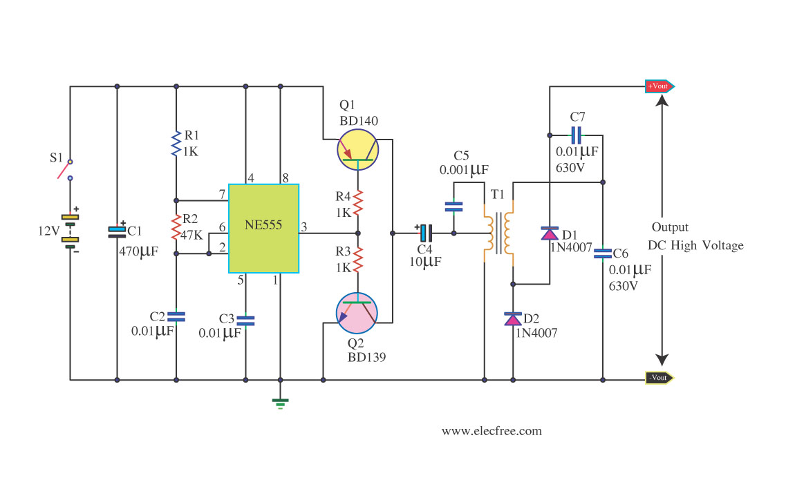
This circuit is a DC to DC inverter that can convert a 12V DC battery voltage to a high voltage of 300V DC. This circuit operates with low current. This DC to DC inverter circuit is designed to efficiently step...
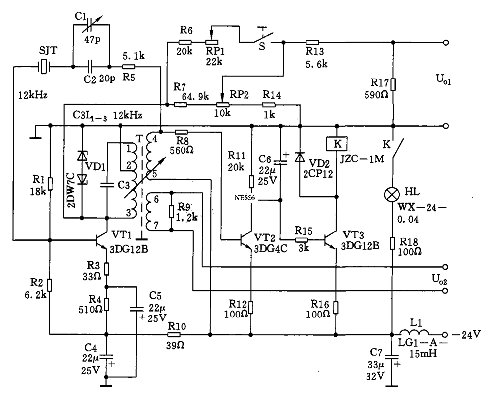
The circuit features a 12kHz intermediate frequency (IF) oscillator utilizing a quartz crystal for precision frequency generation. It includes components for output level adjustment, a level-up circuit, and an alarm circuit. The design employs a unique single-tuned variable feedback...
This circuit design for a high-frequency waveform generator is highly beneficial for electronic experiments and designs. The circuit generates sine wave oscillations, but it can also be modified to produce triangle or square wave functions. The high-frequency waveform generator circuit...
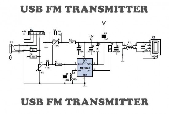
This is a simple USB FM transmitter designed to play audio files from an MP3 player or computer on a standard VHF FM radio. The USB FM transmitter operates by converting audio signals from a digital source, such as an...