
Low-Power Switching Regulator

The low-power switching regulator circuit is designed to convert a higher input voltage, specifically 9V, to a regulated output voltage of 5V. This type of regulator is particularly useful in applications where power efficiency is critical, such as in battery-powered devices or energy-sensitive applications.
The circuit typically consists of several key components: an inductor, a switch (often a transistor), a diode, and capacitors. The operation of the switching regulator can be described in two main phases: the on-phase and the off-phase.
During the on-phase, the switch is closed, allowing current to flow from the input voltage source through the inductor. As the current flows, energy is stored in the magnetic field of the inductor. The inductor's current builds up, and the voltage across it increases. The output capacitor also begins to charge during this phase.
When the switch is opened (off-phase), the current through the inductor cannot change instantaneously. The inductor will attempt to maintain the current flow, and the energy stored in the inductor is released through the diode to the output capacitor. This process results in a smooth and regulated output voltage of 5V.
The efficiency of the regulator is influenced by several factors, including the choice of components, the switching frequency, and the load conditions. High-efficiency switching regulators can achieve efficiencies of over 90%, significantly reducing power losses compared to linear regulators.
In summary, the low-power switching regulator circuit is an essential component in modern electronics, providing a reliable means of voltage regulation while maintaining high efficiency. Proper design considerations and component selection are crucial for optimizing performance and ensuring the circuit meets the desired specifications.A circuit of low-power switching regulator is shown in the schematic diagram below. This circuit can give output voltage of 5V from 9-V source. The efficiency.. 🔗 External reference
Related Circuits
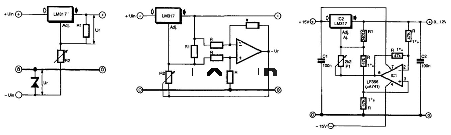
The unique feature of this regulator is that the output voltage can be adjusted down to 0 V. The regulation is provided by an integrated regulator type LM317. Typically, in supplies that can be adjusted to 0 V, this...
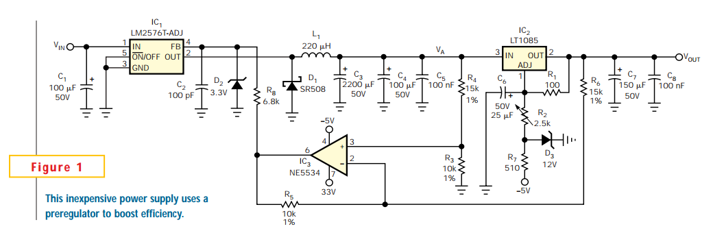
Linear regulators are easy to implement and have better noise and drift characteristics than switching approaches. Their largest disadvantage is inefficiency: excess energy dissipated as heat. Several well-known techniques are available to minimize the input-to-output voltage across a linear...
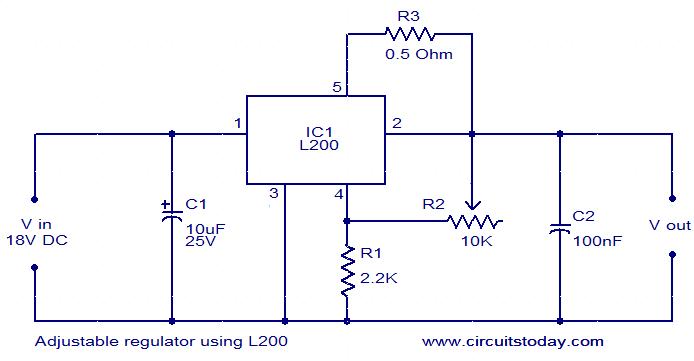
The circuit diagram depicts an adjustable voltage regulator utilizing the IC L200. The L200 is a monolithic integrated adjustable voltage regulator IC that incorporates features such as current limiting, thermal shutdown, power limiting, and input over-voltage protection. This regulator...
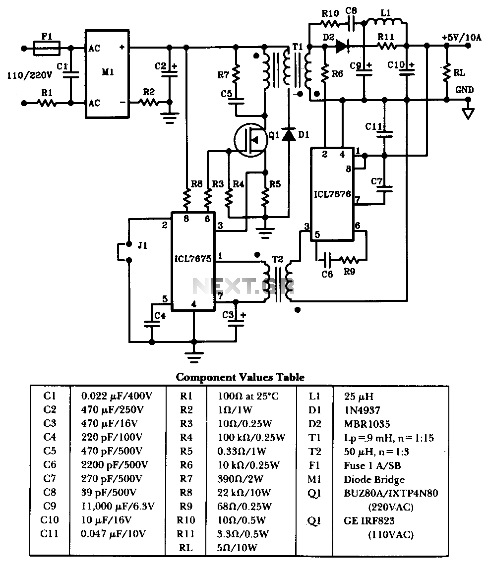
The schematic illustrates a 50W power supply providing a 5V, 10A output. It operates as a flyback converter in continuous mode. The circuit incorporates both primary and secondary side controllers, offering full protection against fault conditions such as overcurrent....
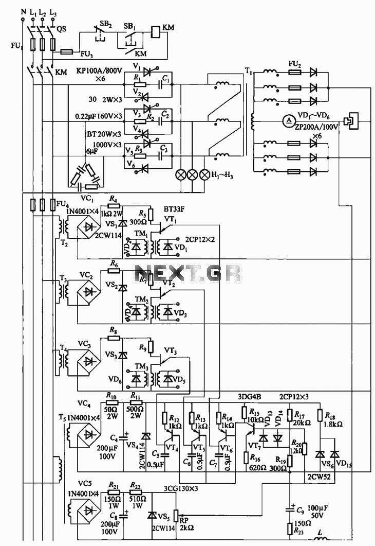
The 300A-18V three-phase thyristor power regulator circuit is designed for electrolysis applications. It can output a direct current of 3000A at an adjustable voltage of 18V, providing a power supply solution for various processing needs. The circuit comprises a...
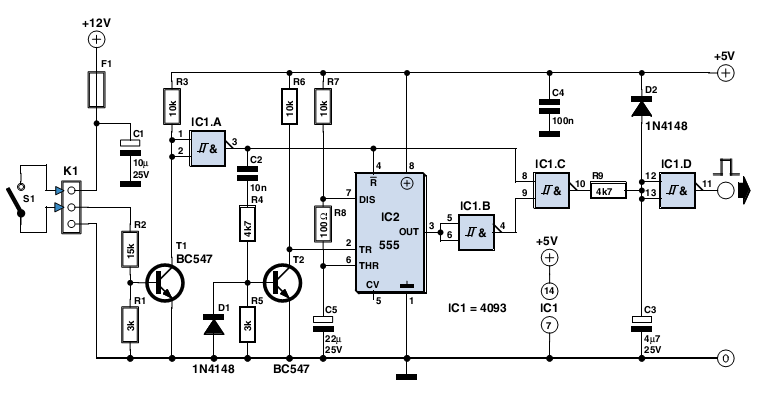
The circuit described here was designed as an addition to a remotely controlled garage door opener. The problem was that a brief burst of interference, arising from a thunderstorm or a mains spike, was enough to trigger the mechanism,...