
LM555 Timer Delay Signal Clock Circuit

The LM555 timer is a versatile integrated circuit widely used in various timer, delay, pulse generation, and oscillator applications. In this specific configuration, the circuit utilizes two stages to enhance its functionality. The first stage is responsible for generating a precise pulse width, while the second stage manages the delay period between pulses.
The circuit is typically configured in astable or monostable mode, depending on the desired output behavior. In astable mode, the LM555 continuously oscillates between high and low states, generating a square wave output. This configuration is ideal for applications such as clock pulses, LED flashers, or tone generation.
In monostable mode, the LM555 produces a single pulse of a specified duration in response to a trigger input. This mode is useful for applications requiring a timed response, such as timer circuits or event counters.
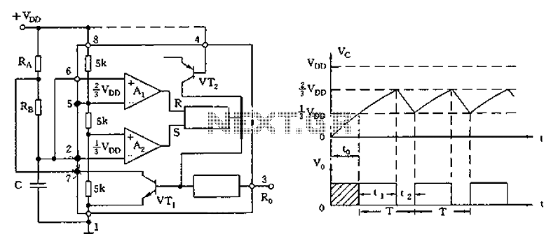
Key components in the circuit include resistors and capacitors that determine the timing characteristics. The pulse width is primarily influenced by the values of the resistors and the capacitor connected to the discharge and threshold pins of the LM555. Similarly, the delay period can be adjusted by modifying the component values in the feedback loop.
Overall, the dual-stage design of this LM555 timer circuit enhances its versatility, allowing for precise control over both pulse width and delay, making it suitable for a wide range of electronic applications.LM555 timer circuit is similar to the one above but employs two stages so that both the pulse width and delay can be controlled 🔗 External reference
Related Circuits

The input capacitor is used for low-frequency cut-off, with a standard value of 0.1 µF, resulting in a cut-off frequency of approximately 16 Hz. The input capacitor plays a critical role in electronic circuits, particularly in signal processing and audio...
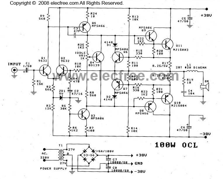
This OCL 100W power amplifier offers excellent sound quality. The circuit features direct coupling throughout to minimize low-frequency cut-off issues, enhancing super bass performance. The input signal for the tone controls enters via capacitor C1 to the base pin...
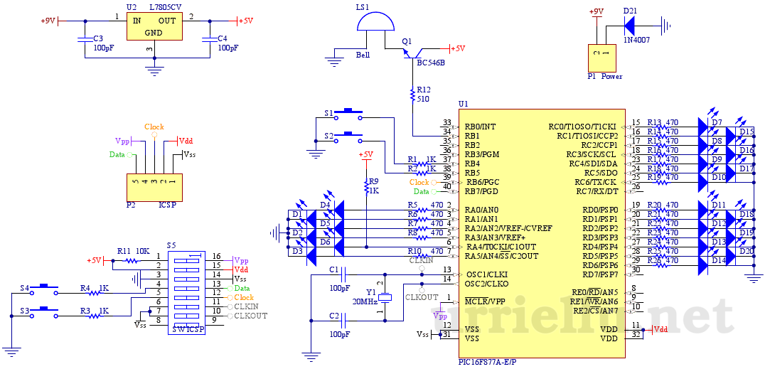
This is the first electronic circuit designed from scratch, marking the initial experience with programming a microcontroller (MCU), the first application written in assembly language, and the second homemade printed circuit board (PCB). While it is common for individuals...
The circuit diagram illustrates the 555 timer (or 556 timer in half configuration) configured in astable multivibrator mode. It features three resistive and capacitive elements connected as shown. In one-shot mode, the trigger terminal (pin 2) is connected to...
This is a useful instrument for workshops. The standard of the produced frequencies is 10 to 1. The basic frequency is produced by a crystal with high accuracy. The circuit consists of the oscillator, around the crystal and the...
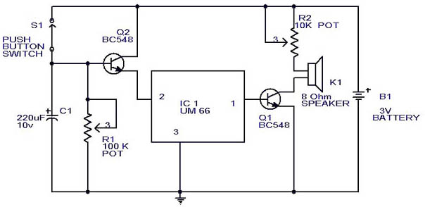
This circuit is a slight modification of a previous design. In the earlier version, the switch needed to be held down for the entire duration of the music playback. In this updated circuit, pressing the push button once charges...