
Luxeon Star LED driver with MAX1709 IC
Drive is not appropriate to turn a normal power supply connection. Power consumption is already so large that we had used a robust switch. However, any contact resistance significantly worse performance. The switch circuit can be used outlets ONA (1) and ONB (16). When she was in the level of ONB in ??L and H levels, the circuit is in standby mode and the drive is off. In all other combinations is enabled. Quiescent current I measured about 30 microamps. In this current, the battery should be discharged for several years, his own self-discharge rate is usually higher.
The inverter feeds the white Luxeon Star LEDs with up to 1 watt of input power supply LEDs are very close to the output voltage. LED powered from the power source is not ideal. The LED is quite hot during operation. After heating, the threshold voltage reduces the power LED and the current increases. This phenomenon is partly limited by connecting resistor R2 to R4 in series with LEDs. Unfortunately, LED voltage (at rated current) as well as by the manufacturer and production batch, but generally is in the range of 3.3 to 3.4 V. The first manned sample flowed LEDs switch current about 250 mA after warm-up current is increased about 320 mA. The other two lamps, the supply voltage is 3.3 V too small and the LED current was switched on for only 150 and 180 mA. Output voltage to be slightly larger. This could be done using external dividers. Fortunately, there is an easier way. Voltage control circuit is taken at the OUT pin (9). It did so to increase the resistor R1 through which the circuit is energized at 27, respectively. 39 ohms. Private consumption MAX circuit is about 4 mA. The measured data is an order of magnitude greater than current supply in entire sheet. Increases Where R1 from 2.2 to 27 ohms, the voltage drop on R1 about 108 mV and this decline also increases the output voltage. Voltage stability worsens as the supply current of the converter is also partly dependent on operating conditions. In the case of the LED drive is the output voltage regulation is satisfactory. With the involvement of R1 in parallel with the NTC thermistor with a suitable resistor (47-100 watts), can partially compensate for the temperature dependence of LEDs. The drive for the lamp is built on a printed circuit board according to Figure 2 and 3. Topology of the board is quite critical. If you design your own for this circuit board, make sure that the wires from the coil, diode and filter capacitor circuits have been minimized. Most of the SMD components and soldered joints by. From the other side of the plate is a switch, LED, and battery charging plug. To minimize the voltage drop at the inlet, it is appropriate to use the battery terminals with tape, which p?ipájejí directly to the board. To recharge the battery charger is a standard used to have them for charging the lamp cable connection.
The used parts are subject to large claims. Filter capacitors should have very low series resistance (ESR), the coil must have a saturation current of 1.5 A. The LED I could find the appropriate size SMD, I finally used the standard by 1N5822 soldered joints. LEDs have been built in the sample bolted to the plate. In another location, you can shorten the plate. The LED is quite hot during operation; it is therefore suitable for long-term operation be mounted to a piece of sheet metal or metal lamp housing, which will serve as a heat sink.
The album will be filled by components to the resistor R1. Instead of engaging him temporarily resistive trimmer resistance of 100 ohms. Runner turned so that the trimmer had almost minimal resistance. Before connecting the power supply board again thoroughly checked.
To revitalize the appropriate power supply adjustable from 0 V with adjustable output current limitation. The power supply should be connected ammeter before regulatory loop source. The inlet to the cord is normal multimeter, I measured a current of 2 A loss of about 0.5 V. Set voltage 1.25 V and a current limit of 50 to 100 mA. If all goes well, will turn on the lamp flicker or poorly lit. Turn off the lamp switch on the lamp and current limiting on the power set at 2 A. Turn on the flashlight. LED should now intensify light, the current consumption from 0.5 to 1.5 A. Measure the voltage on R2 (R3, R4). Involved instead of trimmer R1 R2 set the voltage of 80-90 mV. This corresponds to the current 270-300 mA. Unplug the lamp, unplug the trimmer and measure its resistance. Instead of R1, then plug the resistor with a resistance corresponding approximately to the measured resistance trimmer. Resistor R1 recommend increasing too. Not enough to increase its resistance to 39 ohms, you can increase the voltage on the LED shorting resistors R2 to R4. If you have a suitable power source, use the first phase of the current revival of almost empty article in the second phase of the charged NiCd or NiMH batteries.
Parts List
R1 2.2 to 39 ohm see text SMD 0805 R2, R3, R4 1 Ohm SMD 1206 C1 to C4 100 uF SMD Tantalum C5 100 nF SMD 1206 C6 220 nF SMD 1206 C7, C8 100 nF SMD 0805 L1 2.2 ?H, 1.5 A SMD D1 1N5822 LED LXHL-NW98 Luxeon Star IC1 MAX1709 SW1 switch "Turbo" from PC J1 Connector 3.4 x 1.3 mm or 3.8 x 1 mm Tantalum capacitor of 100 uF low ESR and coil at the company Spezial Electronic Hotel Prague p. 200, Susicka 20, Prague 6, www.spezial.cz. LED Luxeon Star LXHL-NW98 (10 ° beam angle, 488, - CZK), or without LED optics RF5X2UWT4-B4 (60 °, 198, - CZK, prices VAT incl.) Switch and the electronic GM, www.gm. com. MAX1709 Circuit for 250 CZK (including VAT) for businesses Elix, Klapkova 48, Prague 8 - Kobylisy www.elix.cz. Miniature power connector 1 or 3.8 x 3.4 x 1.3 mm at the firm peat, French 34, Prague 2 PCB at the joint company, LED current is flowing in these conditions difficult to measure. If you connect to the inlet of the LED meter, there will be a voltage drop on it, which completely distorts the measurement. LED current should be measured as the voltage drop across the resistor R2 to R4. The current is 333 mA through the resistor voltage drop of 100 mV. Figures in millivolts, therefore corresponds to approximately expressed as a percentage of maximum power. Maximum continuous LED current is 350 mA.
The MAX1709 circuit is a step-up converter designed to convert low input voltages to higher output voltages, specifically for portable devices. It can deliver a maximum output current of up to 4 A, making it suitable for powering high-efficiency LEDs such as the Luxeon Star series. The internal architecture includes a control logic circuit, a reference voltage source, and a high-performance switching MOSFET with a low on-resistance of just 10 milliohms, providing high efficiency in power conversion.
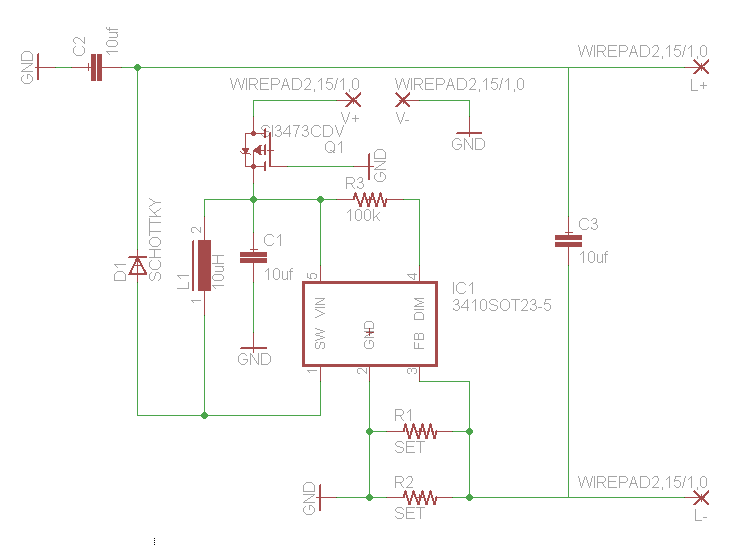
The circuit configuration incorporates essential components such as an inductor, a diode, filtering capacitors, and a resistor, enabling it to function effectively as a power supply for LED applications. The inverter circuit is activated by applying power from a battery through diode D1 and resistor R1 to the OUT pin. The operation begins when the supply voltage exceeds 2.15 V, at which point the circuit transitions to normal mode, and the output voltage is regulated via a feedback loop that compares the voltage across a resistive divider with a fixed reference voltage of 1.24 V.
Output voltage adjustment can be accomplished in two ways: by grounding the FB input for a fixed output of either 3.3 V or 5 V, or by utilizing an external resistive divider to set the output voltage within a range of 2.5 V to 5.5 V. The specific application discussed here maintains a fixed output voltage of 3.3 V.
The design also emphasizes the importance of minimizing contact resistance in the switch circuit, which can adversely affect performance. The quiescent current of the circuit is approximately 30 microamps, allowing for long battery life due to minimal self-discharge.
Thermal management is critical, as the Luxeon Star LEDs can operate at high temperatures, which may affect their performance and lifespan. The use of series resistors R2 to R4 helps mitigate the increase in current due to temperature rise. The circuit layout is crucial for optimal performance, and care must be taken to minimize the lengths of traces connected to the inductor, diode, and filter capacitors to reduce parasitic inductance and resistance.
The parts list includes specific components necessary for assembly, highlighting the need for low ESR capacitors and inductors capable of handling the required current. The assembly instructions emphasize the importance of careful calibration and testing to ensure proper functionality, with suggestions for measuring LED current through voltage drops across resistors rather than direct measurement to avoid distortion.
Overall, the MAX1709-based inverter circuit represents a sophisticated solution for driving high-power LEDs in portable applications, balancing efficiency, performance, and thermal management.Anyone who has ever dealt with construction of low-voltage-fed inverter realized that this is no easy task. The shrinking supply voltage decreases rapidly transferred power and efficiency. Samokmitající converters fail to provide sufficient power to drive control for the purpose of unduly complex.
Involvement of the drive, greatly simplifies the use of special circuits. For describing the lamp with a colleague, we selected the circuit MAXIM, MAX1709 type, which allows the drive to realize the power, exceeding the needs described lamp. Circuit MAX1709 is designed for portable devices for increasing the drive. Depending on the size of input and output voltage is able to supply current to 4 A. The circuit inside the control logic associates, reference source and switching power MOSFET with a channel resistance of closed just 10 milliohms. The circuit just plug coil, diode, filtering and blocking capacitors, one resistor, and the drive is ready.
Involvement of the drive for a lamp is on Figure 1 . Inverter circuit is off-state power from the battery through the diode D1 and R1 to the OUT pin (9). After switching circuit is controlled by an auxiliary oscillator. Only increases when the supply voltage of 2.15 V, the circuit goes into normal mode. Output voltage is controlled by a feedback loop. The voltage from resistive divider is compared with a reference voltage of 1.24 V and the voltage deviation under the control of the power transistor switching time. The output voltage can be adjusted in two ways. If the FB input (10) is grounded, the internal divider circuit. It is fixed to the output voltage of 3.3 or 5 V by the level of the 14th pin Any output voltage can be set between 2.5 to 5.5V by an external divider.
The converter described here is fixed 3.3V output voltage Drive is not appropriate to turn a normal power supply connection. Power consumption is already so large that we had used a robust switch. However, any contact resistance significantly worse performance. The switch circuit can be used outlets ONA (1) and ONB (16). When she was in the level of ONB in ??L and H levels, the circuit is in standby mode and the drive is off.
In all other combinations is enabled. Quiescent current I measured about 30 microamps. In this current, the battery should be discharged for several years, his own self-discharge rate is usually higher. The inverter feeds the white Luxeon Star LEDs with up to 1 watt of input power supply LEDs are very close to the output voltage.
LED powered from the power source is not ideal. The LED is quite hot during operation. After heating, the threshold voltage reduces the power LED and the current increases. This phenomenon is partly limited by connecting resistor R2 to R4 in series with LEDs. Unfortunately, LED voltage (at rated current) as well as by the manufacturer and production batch, but generally is in the range of 3.3 to 3.4 V. The first manned sample flowed LEDs switch current about 250 mA after warm-up current is increased about 320 mA.
The other two lamps, the supply voltage is 3.3 V too small and the LED current was switched on for only 150 and 180 mA. Output voltage to be slightly larger. This could be done using external dividers. Fortunately, there is an easier way. Voltage control circuit is taken at the OUT pin (9). It did so to increase the resistor R1 through which the circuit is energized at 27, respectively. 39 ohms. Private consumption MAX circuit is about 4 mA. The measured data is an order of magnitude greater than current supply in entire sheet. Increases Where R1 from 2.2 to 27 ohms, the voltage drop on R1 about 108 mV and this decline also increases the output voltage.
Voltage stability worsens as the supply current of the converter is also partly dependent on operating conditions. In the case of the LED drive is the output voltage regulation is satisfactory. With the involvement of R1 in parallel with the NTC thermistor with a suitable resistor (47-100 watts), can partially compensate for the temperature dependence of LEDs.
The drive for the lamp is built on a printed circuit board according to Figure 2 and 3 . Topology of the board is quite critical. If you design your own for this circuit board, make sure that the wires from the coil, diode and filter capacitor circuits have been minimized. Most of the SMD components and soldered joints by. From the other side of the plate is a switch, LED, and battery charging plug. To minimize the voltage drop at the inlet, it is appropriate to use the battery terminals with tape, which p?ipájejí directly to the board.
To recharge the battery charger is a standard used to have them for charging the lamp cable connection. The used parts are subject to large claims. Filter capacitors should have very low series resistance (ESR), the coil must have a saturation current of 1.5 A.
The LED I could find the appropriate size SMD, I finally used the standard by 1N5822 soldered joints. LEDs have been built in the sample bolted to the plate. In another location, you can shorten the plate. The LED is quite hot during operation, it is therefore suitable for long-term operation be mounted to a piece of sheet metal or metal lamp housing, which will serve as a heat sink.
The album will be filled by components to the resistor R1. Instead of engaging him temporarily resistive trimmer resistance of 100 ohms. Runner turned so that the trimmer had almost minimal resistance. Before connecting the power supply board again thoroughly checked. To revitalize the appropriate power supply adjustable from 0 V with adjustable output current limitation. The power supply should be connected ammeter before regulatory loop source. The inlet to the cord is normal multimeter, I measured a current of 2 A loss of about 0.5 V. Set voltage 1.25 V and a current limit of 50 to 100 mA. If all goes well, will turn on the lamp flicker or poorly lit. Turn off the lamp switch on the lamp and current limiting on the power set at 2 A. Turn on the flashlight. LED should now intensify light, the current consumption from 0.5 to 1.5 A. Measure the voltage on R2 (R3, R4). Involved instead of trimmer R1 R2 set the voltage of 80-90 mV. This corresponds to the current 270-300 mA. Unplug the lamp, unplug the trimmer and measure its resistance. Instead of R1, then plug the resistor with a resistance corresponding approximately to the measured resistance trimmer.
Resistor R1 recommend increasing too. Not enough to increase its resistance to 39 ohms, you can increase the voltage on the LED shorting resistors R2 to R4. If you have a suitable power source, use the first phase of the current revival of almost empty article in the second phase of the charged NiCd or NiMH batteries.
Parts List R1 2.2 to 39 ohm see text SMD 0805 R2, R3, R4 1 Ohm SMD 1206 C1 to C4 100 uF SMD Tantalum C5 100 nF SMD 1206 C6 220 nF SMD 1206 C7, C8 100 nF SMD 0805 L1 2.2 ?H, 1.5 A SMD D1 1N5822 LED LXHL-NW98 Luxeon Star IC1 MAX1709 SW1 switch "Turbo" from PC J1 Connector 3.4 x 1.3 mm or 3.8 x 1 mm Tantalum capacitor of 100 uF low ESR and coil at the company Spezial Electronic Hotel Prague p. 200, Susicka 20, Prague 6, www.spezial.cz . LED Luxeon Star LXHL-NW98 (10 ° beam angle, 488, - CZK), or without LED optics RF5X2UWT4-B4 (60 °, 198, - CZK, prices VAT incl.) Switch and the electronic GM, www.gm.
com . MAX1709 Circuit for 250 CZK (including VAT) for businesses Elix, Klapkova 48, Prague 8 - Kobylisy www.elix.cz . Miniature power connector 1 or 3.8 x 3.4 x 1.3 mm at the firm peat, French 34, Prague 2 PCB at the joint company, LED current is flowing in these conditions difficult to measure.
If you connect to the inlet of the LED meter, there will be a voltage drop on it, which completely distorts the measurement. LED current should be measured as the voltage drop across the resistor R2 to R4. The current is 333 mA through the resistor voltage drop of 100 mV. Figures in millivolts, therefore corresponds to approximately expressed as a percentage of maximum power.
Maximum continuous LED current is 350 mA. 🔗 External reference
Related Circuits
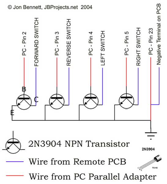
This project article was originally written in 2004 when most computers had parallel ports. This is no longer the case, so much of this information is now outdated. The Mini RC Car Project has been one of the most...
How would you like free boost driver designs? Although it is not possible to control anyone's actions, any individual interested in selling this circuit would be appreciated. The boost driver circuit is a type of DC-DC converter designed to step...
Designs for audio amplifiers with DC coupling to the load are not commonly seen today, despite their clear benefits. One advantage... Audio amplifiers utilizing DC coupling to the load present several notable advantages in specific applications. DC coupling allows for...

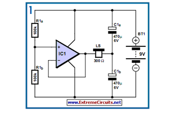
This circuit is a voltage-controlled oscillator (VCO) that utilizes the 555 timer integrated circuit (IC) as its primary component. The 555 timer is configured as an astable multivibrator, enabling it to function as an oscillator. An astable multivibrator is...
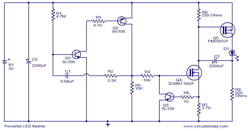
This circuit diagram illustrates a powerful LED flasher utilizing a 1W high power LED, which is widely available in the market. Transistors Q1 and Q2 are configured as an oscillator that generates positive pulses with a duration of 20...
A highly practical workbench lighting unit designed for electronics hobbyists. The portable inspection lamp circuit features an onboard voltage regulator and a high-brightness 5mm white LED. It can be powered by any 9 to 18 volt DC-rated AC mains...