
Cycle 100 MHz frequency counter circuit diagram
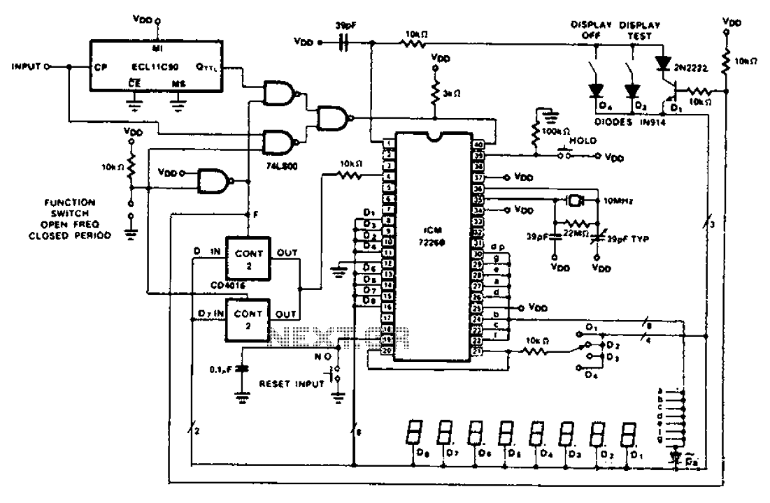
The CD4016 is a quad bilateral switch that allows for the simultaneous control of multiple analog signals. Each switch in the CD4016 is controlled by a digital signal, enabling the selection of input signals based on the logic levels applied. This capability makes it suitable for applications requiring the multiplexing of signals without the necessity of additional level shifting circuitry, thereby simplifying the design and reducing component count.
In scenarios where the CD4016 may not meet specific requirements, the CD4051 or CD4052 can serve as viable alternatives. These devices are also analog multiplexers/demultiplexers, capable of routing multiple input signals to a single output or vice versa. The CD4051 can handle up to eight inputs, while the CD4052 can manage two sets of four inputs, providing flexibility based on the application needs.
When integrating these components with an ICM7226, which is a high-performance analog-to-digital converter (ADC), it is essential to ensure that the selected multiplexer aligns with the input signal characteristics and the desired sampling rate. Proper configuration and selection of the appropriate multiplexer will contribute to optimal system performance, ensuring accurate signal representation and minimal distortion during the analog-to-digital conversion process.
In summary, the CD4016, CD4051, and CD4052 play crucial roles in multiplexing applications, particularly in conjunction with devices like the ICM7226, facilitating efficient signal management in digital systems. As shown, a CD4016 analog instrument is used here as a multiple multiplexed digital output, these output transfer function back to the input. Since the CD4016 is a digitally co ntrolled analog transmission gate, so do not need a digital electrical output level shift. CD4051 or CD4052 can also be used to select the appropriate input ICM7226 multiplexed input.
Related Circuits
Detects the amount of salt contained in liquid foods, featuring a three-level LED indicator. This circuit is designed to detect the approximate percentage of salt concentration. The salt detection circuit operates by utilizing a conductivity sensor that measures the ionic...
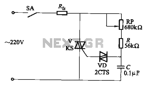
The adjustment potentiometer RP allows for the modification of the TRIAC conduction angle, facilitating temperature control applications. The adjustment potentiometer (RP) serves a crucial role in controlling the conduction angle of the TRIAC, which in turn regulates the power delivered...
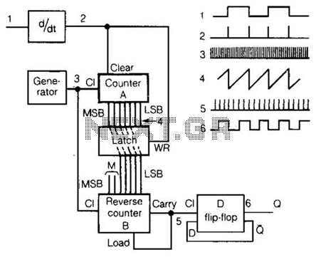
An input rectangular signal is differentiated to produce short impulses from its edges. These impulses transfer the content of counter A to a latch that clears the counter after a very brief period. Counter A counts impulses at a...
This light sensor switch circuit enables the automatic activation of a lamp when ambient light levels are low, such as during nighttime. The circuit keeps the lamp illuminated for a predetermined duration. When transistors T4 and T5 are activated,...
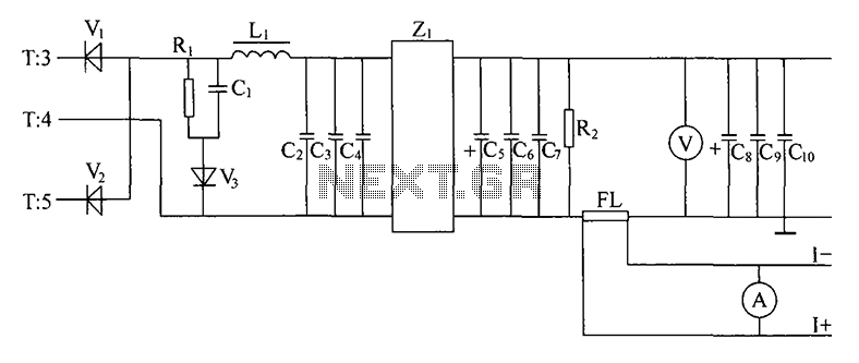
Alternating positive and negative voltage pulses from the secondary winding of a high-frequency transformer (T) are full-wave rectified by high-frequency switching diodes (V1, V2). The output is then filtered through inductors (L1) and capacitors (C2, C3, C4) which form...
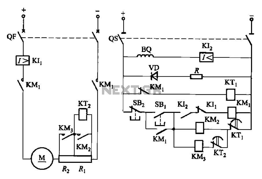
The circuit illustrated in Figure 3-191 features a DC motor armature circuit that includes two series startup resistors, Ri and Rz. The operation of the motor is controlled using buttons for starting and stopping. During the startup phase, two...