
Methods of changing inductance
The schematic illustrates a saturable-core reactor, which is a type of inductor that utilizes a magnetic core whose permeability can be altered by the magnetic field created by its windings. In this circuit, L1 is the primary component, serving as the saturable-core reactor. The control winding, consisting of five loops, is responsible for regulating the magnetic field within the core, thereby influencing the reactor's inductance. The load winding, consisting of three loops, is connected to the load and is affected by the changes in inductance dictated by the control winding.
The presence of the iron core, indicated by the double bar between the inductors, enhances the magnetic coupling between the windings, allowing for efficient energy transfer. The saturable-core symbol, which intersects the two windings, signifies that these windings are magnetically linked through the core. This configuration allows for effective control of power flow, making saturable-core reactors suitable for applications such as voltage regulation and power conditioning in electrical systems.
In practical applications, the operation of the saturable-core reactor involves adjusting the current through the control winding to modulate the core's saturation level. This modulation can lead to changes in the impedance seen by the load, which can be utilized for various control strategies in power electronics. The design and implementation of such circuits require careful consideration of parameters such as the core material, winding turns, and operating frequency to ensure optimal performance and reliability.The schematic diagram of this circuit is shown in figure 3-33. L1 is the schematic symbol for a saturable-core reactor. The control winding is shown with five loops, and the load winding is shown with three loops. The double bar between the inductors stands for an iron core, and the symbol that cuts across the two windings is a saturable-core symbol indicating that the two windings share a saturable core. 🔗 External reference
Related Circuits
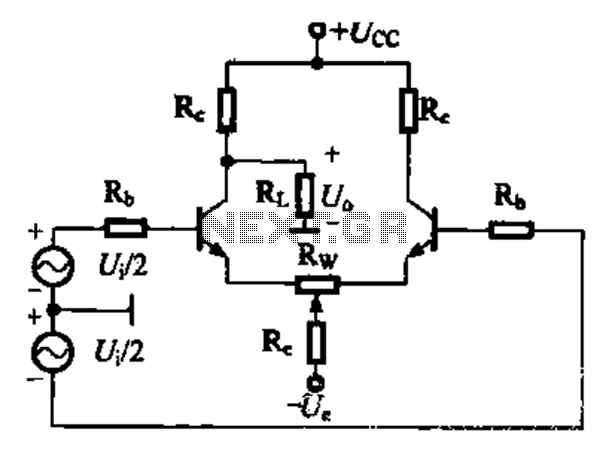
A comparison of four connection methods and features of a differential amplifier circuit is presented. The circuit demonstrates a magnification of a single tube with half the earnings, effectively countering common-mode negative feedback effects. The Common-Mode Rejection Ratio (CMRR)...
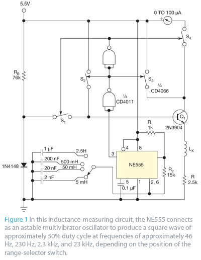
Bipolar junction transistors transfer a current from a lower-resistance emitter to a higher-resistance collector. This property can be utilized to measure inductance. Bipolar junction transistors (BJTs) are semiconductor devices that play a crucial role in electronic circuits by enabling the...
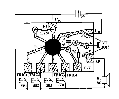
Constantly changing light and sound analog controller circuit 07 The circuit described is an analog controller designed to modulate light and sound in a dynamic manner. This circuit utilizes various electronic components to create an interactive experience where both light...
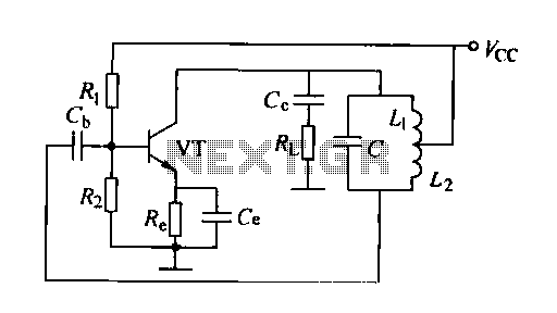
A feedback oscillator circuit utilizing inductance is presented, featuring the 3DG3 transistor. The component parameters reference values include: 1) transistors 3DG6, 2) resistances R1 at 91 kΩ, R2 at 11 kΩ, and R3 unspecified, 3) capacitance values of C...
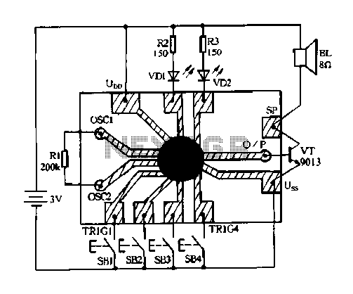
Constantly changing light and sound analog controller circuit 04 The circuit designated as the "Constantly Changing Light and Sound Analog Controller Circuit 04" is designed to modulate both light and sound outputs in a dynamic manner. This type of...
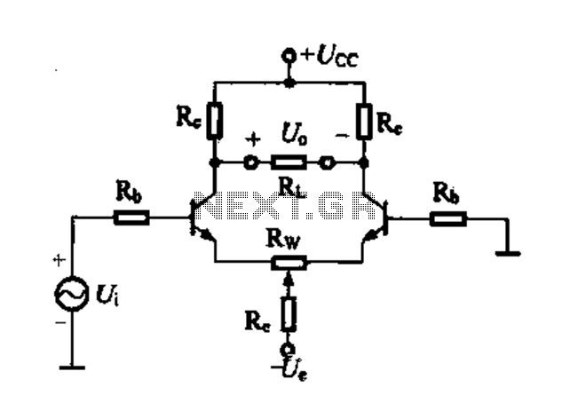
Differential amplifier circuit with four connection methods and characteristics for comparison. The circuit exhibits magnification with a single tube when symmetrical. Additionally, CMRR (Common Mode Rejection Ratio) is adapted from single-ended input to a double-ended output. The differential amplifier is...