
Metronome II

The described circuit consists of two main functional blocks: a multivibrator and an audio amplifier. The multivibrator, typically configured as an astable multivibrator, produces a square wave output that corresponds to the desired beat frequency. The frequency of oscillation is determined by the values of resistors and capacitors in the circuit, along with the setting of the potentiometer, which allows for fine-tuning of the output frequency within the specified range of 40 to 200 beats per minute.
The audio amplifier stage is connected to the output of the multivibrator. This stage is designed to amplify the weak square wave signal generated by the multivibrator to a level suitable for driving speakers or other audio output devices. Commonly, an operational amplifier (op-amp) or a dedicated audio amplifier IC is employed for this purpose. The gain of the amplifier can be adjusted using feedback resistors, ensuring that the output signal maintains clarity and fidelity without distortion.
Power supply considerations for the circuit are essential, as both the multivibrator and audio amplifier require a stable voltage source to function effectively. Bypass capacitors may be included near the power supply pins of the ICs to filter out any noise and ensure stable operation.
In summary, this circuit effectively combines a multivibrator for beat generation with an audio amplifier for output enhancement, providing a versatile solution for applications requiring adjustable rhythmic sound. The design allows for user-friendly adjustments and can be utilized in various electronic projects, including metronomes, sound effects generators, or rhythm-based applications.This simple circuit uses a multivibrator to generate the beats and a subsequent audio amplifier stage to increase the output level. Range of adjustment is approximately from 40 to 200 beats per minute set by the gauged potentiometer.
Related Circuits
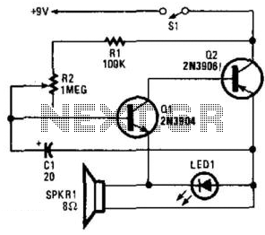
Two complementary transistors create a basic oscillator with a frequency range of approximately 0.5 to several Hz. This circuit serves as a metronome, timer, or pacer for exercise equipment. The oscillator circuit utilizes a pair of complementary transistors, typically one...
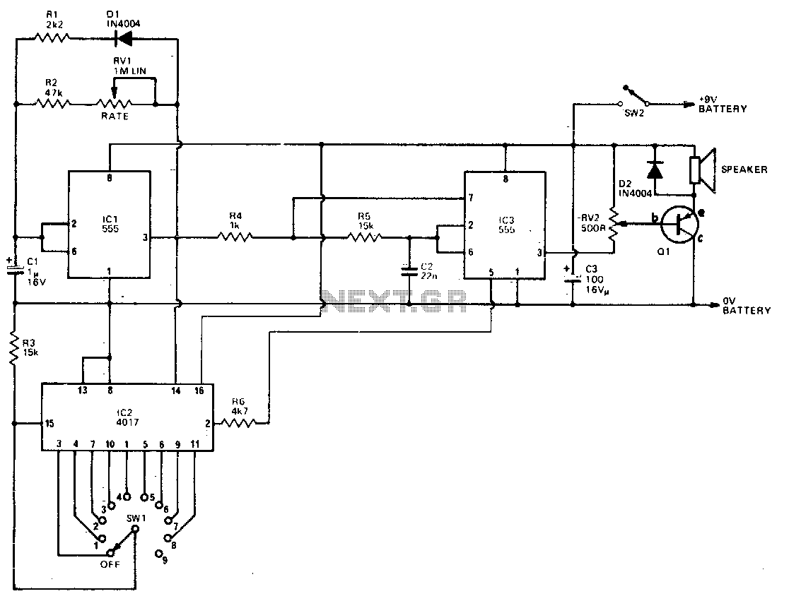
IC3 functions as an oscillator that activates when the output of IC1 is high. The circuit generates two frequencies, approximately 800 Hz and 2500 Hz, based on the component values used. The output from IC3 is buffered by Q1,...
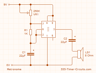
This circuit employs the 555 timer configured in astable mode to produce a continuous square wave output from Pin 3. The output is subsequently filtered through a 22.5 µF electrolytic capacitor to generate a smooth oscillation, resulting in a...
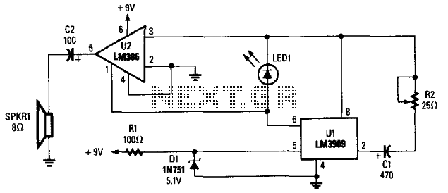
The LM3909 is configured such that the frequency of oscillation relies on a single RC timing circuit, which includes capacitor C1 and resistor R2. LED1 discharges capacitor C1, and the resulting pulse is directed to both pin 3 and...
This mini metronome provides a linearly scaled output with a range of 40 to 208 beats per minute. The transistors Q1 and Q2 facilitate the linear frequency variation of IC1. The described mini metronome circuit utilizes an integrated circuit (IC1)...
The figure illustrates a simple project schematic of a metronome. A metronome is a device utilized by musicians to produce continuous beats through a speaker. The metronome circuit typically consists of several key components that work together to generate a...