
Accentuated beat metronome

The second output of IC2 is connected to the control input of IC3, allowing for frequency modulation. Consequently, the first tone produced is at a high frequency, followed by a low frequency for the second tone, and the third to tenth tones revert to high frequency. This results in a 9-to-1 beat pattern. For instance, if the fifth output is linked to the reset function, the sequence will produce a high tone for the first, low for the second, high for the third and fourth, and upon the fifth output going high, the sequence resets back to the initial high tone. This configuration yields a pattern of three high tones followed by one low tone, or a 3-to-1 beat.
The oscillator IC3, which operates under the control of IC1, is critical for generating the audio tones utilized in the circuit. The frequencies produced are determined by the timing components associated with IC3, enabling the design to produce distinct audible signals that can be adjusted based on user preferences. The buffering stage provided by Q1 ensures that the speaker receives a clean and amplified signal, enhancing the sound output quality.
The decade counter IC2 plays a pivotal role in managing the sequence of tones. It effectively divides the input clock signal from IC1, generating a series of outputs that can be used to control the frequency and duration of the audio tones. The ability to connect the outputs of IC2 to other parts of the circuit, such as the reset function, allows for complex rhythmic patterns to be created, enhancing the versatility of the design. The adjustable components RV1 and R1 afford the user flexibility in customizing the beat intervals and tone lengths, making the circuit suitable for various applications including alarms, sound effects, or musical notes.
Overall, the integration of these components creates a robust and flexible audio generation system, capable of producing a variety of rhythmic patterns and sound frequencies based on user-defined parameters.IC3 acts as an oscillator which operates if the output of ICl is high. With the values used the two frequencies produced are about 800 Hz and 2500 Hz. The output is buffered by Ql which drives the speaker. The first IC is used to generate the tone duration and the time interval between beats. The interval is adjustable by RVl while the tone duration is set by Rl. The output of ICl also clocks IC2, a decade counter with 10 decoded outputs. Each of these outputs go high in sequence on each clock The second output of IC2 is connected to the control input of IC3 and is used to change the frequency. Therefore the first tone will be high frequency, the second low and the third to tenth will be high again.
This gives the 9-1 beat. If for example the 5th output is connected to the reset, the first tone will be high, the second low, and the third and fourth high, then when the 5th output goes to a high it resets it back to the first which is a high tone. We then have 3 high and one low tones or a 3-1.
Related Circuits
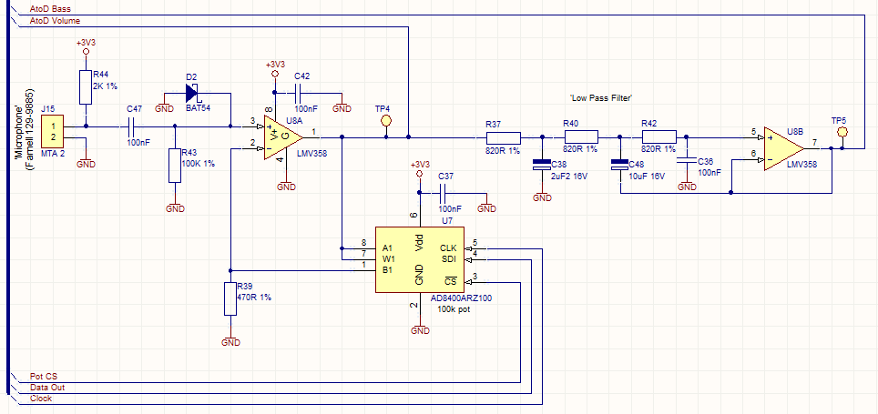
This circuit employs a digital potentiometer to enable the microcontroller to automatically adjust the circuit's gain according to the ambient audio volume. However, a standard potentiometer can be used if automatic adjustment is unnecessary. The low-pass filter design is...
One of the simplest methods of metal detecting is through a beat frequency oscillator. The circuit consists of two balanced oscillators: one provides a reference signal, while the other acts as the detector element. The frequency of the reference...
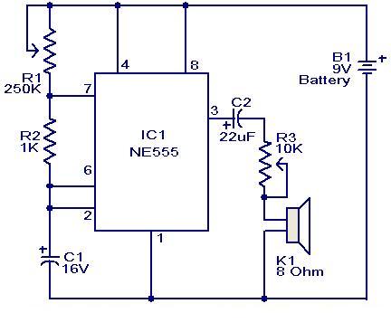
This weblog focuses on electronic circuit schematics, PCB design, DIY kits, and diagrams for electronic projects. A simple circuit utilizing the NE555 IC is presented, which can be employed to generate metronomes. This circuit is particularly beneficial for music...
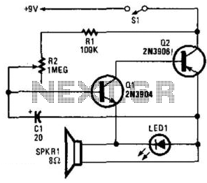
Two complementary transistors create a basic oscillator with a frequency range of approximately 0.5 to several Hz. This circuit serves as a metronome, timer, or pacer for exercise equipment. The oscillator circuit utilizes a pair of complementary transistors, typically one...
The metronome circuit has been assembled multiple times without success. Two manufacturers of the 555 timer, ON Semiconductor and National Semiconductor, provide circuit designs that differ from the original. In their designs, pins 2, 6, and 7 are not...
This mini metronome provides a linearly scaled output with a range of 40 to 208 beats per minute. The transistors Q1 and Q2 facilitate the linear frequency variation of IC1. The described mini metronome circuit utilizes an integrated circuit (IC1)...