
Microphone Pre-Amplifier with Tone Control

To effectively interface a microphone with a power amplifier, an intermediary stage is required to amplify the microphone's low-level signal to a suitable level for the power amplifier. This is typically achieved using a microphone preamplifier. The preamplifier boosts the microphone's output, which can range from a few millivolts to a few hundred millivolts, to a level that meets the input requirements of the power amplifier, usually around 1 Vrms.
The schematic for this setup would typically include a microphone connected to the input of the preamplifier. The preamplifier circuit may consist of operational amplifiers configured in a non-inverting configuration to provide gain. Additional components such as resistors and capacitors can be included to set the gain and filter out noise, ensuring a clean signal is passed to the power amplifier.
The output of the preamplifier would then connect to the input of the audio power amplifier. The power amplifier is designed to drive speakers or other loads, converting the amplified signal from the preamplifier into a higher power output suitable for driving audio systems.
In summary, a microphone preamplifier is essential for bridging the gap between the low-level microphone signal and the higher input requirements of a power amplifier, ensuring optimal audio performance in any audio system.Microphone can`t be directly connected to a power amplifier because the signal is too weak. Standard audio power amplifier accept about 1 Vrms to give a full. 🔗 External reference
Related Circuits
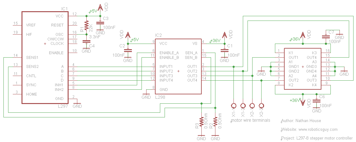
An efficient method for constructing a stepper motor controller involves creating a printed circuit board (PCB) and then placing the components onto it. Once the PCB is fabricated, the assembly and soldering of components is a quick process, especially...
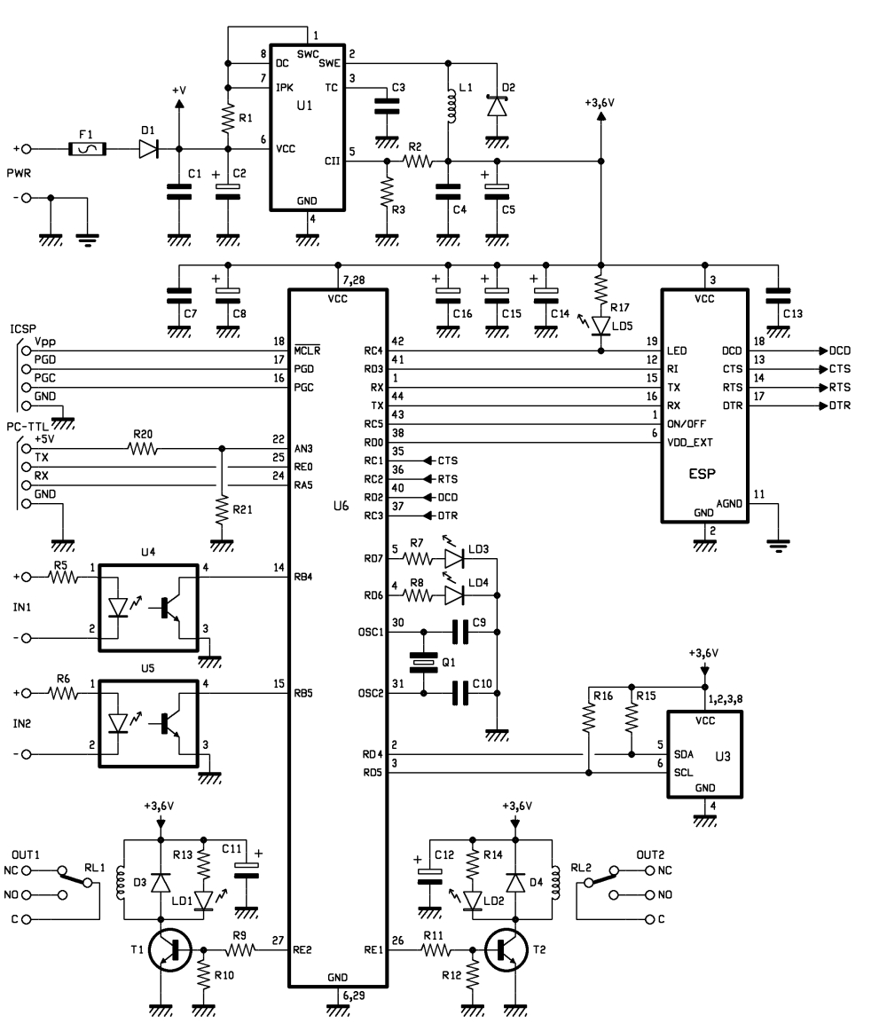
Connected to a burglar alarm or fire alarm, this device facilitates phone calls that play voice messages. It is controlled via DTMF actuators, allowing for immediate operation. In recent years, several telecontrols based on the SIM900 GSM module have...

The adjustment control for the contrast of an LC-Display is typically a 10-kilohm potentiometer. This functions adequately as long as the power supply voltage remains constant. However, in cases where the power supply is not stable (such as with...
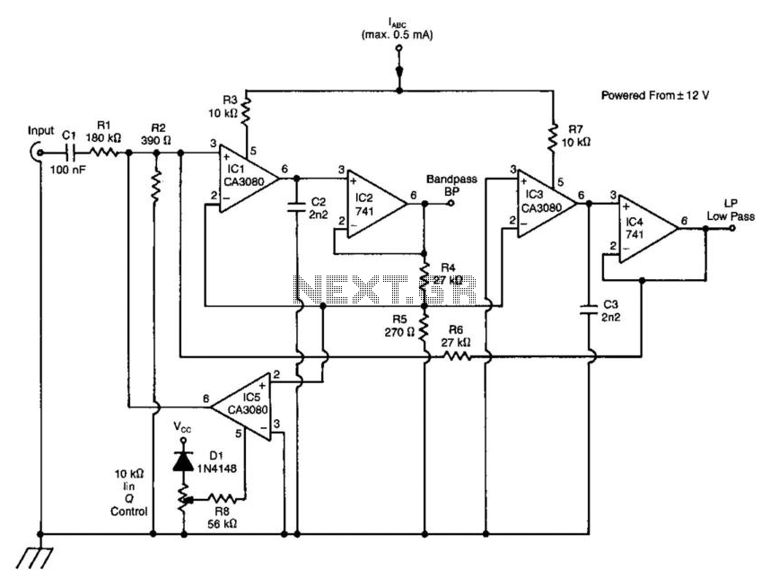
A standard dual integrator filter can be constructed using a few CA3080 operational amplifiers. By varying the parameters L, A, B, and C, the resonant frequency can be swept over a range of 1000:1. At IC1, three current-controlled integrators...
The electric car remote control circuit diagram enables the model car to move forward and backward, as well as turn left and right. It is simple and easy to operate. The radio remote control receiver demodulation circuit utilizes TWH9238...
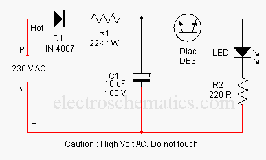
This concept involves generating a flashing light from an LED using alternating current (AC). The circuit is a simple method for flashing one or more LEDs from high voltage direct current (DC) obtained from mains electricity. It can serve...