
multiplexed 7 segment

The circuit utilizes a PIC16F628A microcontroller to control a multiplexed display of four 7-segment LEDs, allowing for the visual representation of a counting mechanism that progresses from 0000 to 9999. The microcontroller's PORTB is employed to drive the segments of the displays, while PORTA is used to select which display is currently active.
The multiplexing technique involves activating one display at a time while rapidly cycling through them to create the illusion that all displays are lit simultaneously. This is achieved by controlling the PORTA pins with a shifting mechanism, where the active display is determined by the `shifter` variable. The `interrupt` function manages the timing and display switching, ensuring that the displays are refreshed at a high frequency to avoid flickering.
The main loop of the program initializes the counter and continuously updates the display based on the current value of the counter. The `mask` function translates the numerical values (0-9) into their corresponding segment states in binary format, which is then stored in the `portb_array`. The counter increments every second, controlled by a delay function, and resets to 0000 once it exceeds 9999.
This design showcases efficient use of microcontroller resources and demonstrates fundamental principles of digital electronics, including binary counting, multiplexing, and real-time control of display devices. The configuration settings ensure proper operation of the microcontroller under specified conditions, allowing for reliable performance in the intended application.The basic technique is the same like the last lesson except fact that we have added a counter which counts between 0000 and 9999. Our counter increments with 1 second delay. /* ` <7465> * ` Lesson nr. 12: ` Multiplexed 7Segment as counter mode ` Done by: ` Aureliu Raducu Macovei, 2010. ` ` This code demonstrates displaying number on fo ur 7-segment display (common ` cathode), in multiplex mode. All 7-segment displays are connected to PORTB ` (RB0. RB7, segment A to RB0, segment B to RB1, etc. ) with refresh via pins ` RA0. RA3 on PORTA. Number is incremented for 1 second. ` To define this project, a counter is added (counts from 0000 to 9999). ` Test configuration: ` MCU: PIC16F628A ` Test. Board: WB-106 Breadboard 2420 dots ` SW: MikroC PRO for PIC 2010 (version v4. 15) ` Configuration Word ` Oscillator: INTOSC:I/O on RA. 6, I/O on RA. 7 ` Watchdog Timer: OFF ` Power up Timer: Disabled ` Master Clear Enable: Enabled ` Browun Out Detect: Enabled ` Low Voltage Program: Disabled ` Data EE Read Protect: Disabled ` Code Protect: OFF ` <7465> * */ //*Header*/ unsigned short mask(unsigned short num) { switch (num) { case 0 : return 0x3F; case 1 : return 0x06; case 2 : return 0x5B; case 3 : return 0x4F; case 4 : return 0x66; case 5 : return 0x6D; case 6 : return 0x7D; case 7 : return 0x07; case 8 : return 0x7F; case 9 : return 0x6F; } } /*Endless mask*/ unsigned short shifter, portb_index; unsigned int digit, number; unsigned short portb_array[4]; void interrupt() { PORTA = 0; // Turn off all 7seg. displays; PORTB = portb_array[portb_index]; // Bring appropriate value to PORTB; PORTA = shifter; // Turn on appropriate 7seg.
display; //move shifter to next digit; shifter <<= 1; if(shifter > 8u) shifter = 1; //increment portb_index; portb_index + ; if (portb_index > 3u) portb_index = 0; //turn on 1st, turn off 2nd 7 seg. ; TMR0 = 0; //reset TIMER0 value; INTCON = 0x20; //clear T0IF, Bit T0IF=0, T0IE=1; } void main() { CMCON |= 7; // Set AN pins to Digital I/O; OPTION_REG = 0x80; // Set timer TMR0; digit = 0; portb_index = 0; shifter = 1; TMR0 = 0; INTCON = 0xA0; // Disable interrupt PEIE, INTE, RBIE, T0IE PORTA = 0; // Turn off both displays TRISA = 0; // All port A pins are configured as outputs PORTB = 0; // Turn off all display segments TRISB = 0; // All port D pins are configured as outputs number = 0; //initial value; do { digit = number % 10u; //extract ones digit; portb_array[0] = mask(digit); //and store it to PORTB array; digit = (number / 10u) % 10u; //extract tens digit; portb_array[1] = mask(digit); //and store it to PORTB array; digit = (number / 100u) % 10u; //extract hundreds digit; portb_array[2] = mask(digit); //and store it to PORTB array; digit = number / 1000u; //extract thousands digit; portb_array[3] = mask(digit); //and store it to PORTB array; Delay_ms(1000); // 1s delay; number + ; //increment number; if (number > 9999u) number = 0; } while(1); //Endless loop; } //End.
🔗 External reference
Related Circuits
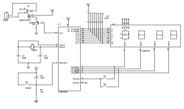
The circuit diagram above illustrates the Clock Controller V1.1. Pins P3.0 to P3.3 are connected to the base of a 4-PNP transistor, specifically the 2N2907, which is used to sink current. The Clock Controller V1.1 circuit is designed to manage...
The lab project involves a BCD counter and a 7-segment display using the CD4510BMS presettable BCD Up/Down Counter. The objective is to count from 32 to 84, rather than the default range of 00 to 99. The current setup...
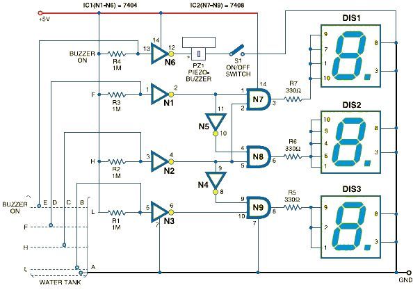
This schematic outlines a straightforward electronic project for designing a water level indicator circuit. It employs a 7-segment display to represent water levels in a tank as low, half, and full, indicated by the letters L, H, and F,...
This design features a signal logic tester that utilizes a common cathode seven-segment display. The display indicates a logic level "1" (represented by an "H" on the display) or a logic level "0" (represented by an "L" on the...

A logic probe is a circuit that indicates the logic state of a node in any TTL logic circuit. It operates when supplied with the same power level. A logic probe is an essential diagnostic tool used in digital electronics...
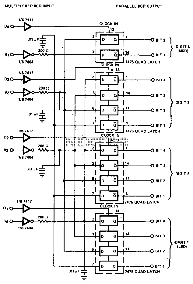
The converter is composed of four quad bistable latches that are activated in the correct sequence by the digit strobe output from the LD110. The complemented outputs (Q) of the quad latch set represent the state of the bit...