
Multivibrator
The multivibrator circuit can be categorized into three main types: astable, monostable, and bistable. Each type serves distinct functions and applications within electronic systems.
The astable multivibrator operates continuously, generating a square wave output without requiring an external trigger. This characteristic makes it suitable for applications such as clock pulse generation and LED flashing circuits. The frequency of oscillation can be adjusted by varying the resistor and capacitor values in the circuit, allowing for flexibility in design.
In contrast, the monostable multivibrator, or one-shot, produces a single output pulse in response to an external trigger. This circuit is commonly used in timing applications where a precise delay is required, such as in timer circuits and pulse width modulation. The pulse width can be modified by changing the values of the timing resistor and capacitor, providing control over the duration of the output signal.
The bistable multivibrator, or flip-flop, maintains its output state until a trigger is received, allowing it to store binary information. This functionality is essential in digital electronics for memory storage and state retention applications. The bistable multivibrator can be implemented using various technologies, including discrete components and integrated circuits, making it versatile for different electronic designs.
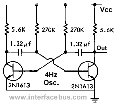
Overall, the multivibrator family of circuits plays a crucial role in timing, signal generation, and data storage in electronic systems. Their versatility and ease of implementation make them fundamental building blocks in both analog and digital electronics.A multivibrator is a form of relaxation oscillator which comprises two stages that are coupled so that the input of one is derived from the output of the other. A multivibrator is basically two amplifier circuits arranged with regenerative feedback. One of the amplifiers is conducting while the other is cut off. The Astablemultivibrator circuit has no stable state. With no external signal applied, the transistors alternately switch from cutoff to saturation at a frequency determined by the RC time constants of the coupling circuits. So an Astable multivibrator could either be called a pulse generator or squarewave generator depending on the value of the resistor and capacitors used in the circuit.
A related IC used is the 555 Timer configured as an 555 Astable multivibrator. The common configuration is to make each side of the circuit identical; The collector resistors R1 and R4 are equal to each other. The Base resistors R2 and R3 are equal to each other. The feedback capacitors C1 and C2 are equal to each other. As soon as power is applied one transistor is assumed to be in saturation while the other transistor is in cutoff.
The time constants are defined by R2C1 and R3C2 which in turn set the high and low periods of the output pulse. The Monostable multivibrator circuit has one stable state; one transistor conducts while the other is cut off.
The term One-Shot is also used to describe the circuit operation. An input signal [the Trigger] must be applied to change this condition. After a period of time, determined by the internal RC components [R2 and C1], a Monostable multivibrator circuit will return to its original condition where it remains until the next trigger signal arrives. This example uses two cross-coupled PNP transistors, with the pulse output derived from Q2. The length of the pulse is equal to 0. 69 x R2 x C1. Additional examples include an IC Multivibrator schematic. A related IC used is the 555 Timer configured as an 555 Monostable multivibrator. Another One-shot IC is the 4098 Monostable multivibrator. A Monostable multivibrator is basically a trigger activated pulse generator. Another example of a monostable multivibrator is a transistor being used for a Pulse Duration Modulator, which also uses a slightly different configuration.
The Bistable multivibrator has two stable states. A Bistable multivibrator remains in one of the stable states until a trigger is applied. The multivibrator then FLIPS to the other stable condition and remains there until another trigger is applied. The multivibrator then changes back (FLOPS) to its first stable state. A type of Toggle flip flop in which the input [T] toggles the output from one state to the next. This circuit generates an FM modulated carrier wave. The audio frequency [AF] input is applied to transformer T1, which is in series with the base return.
This input voltage causes the gate length and fundamental frequency to vary. The amount of change in the amplitude of the audio input determines the frequency variation of the signal. The circuit uses a series tuned circuit composed of C and L. No other values are provided, the circuit is only shown to illustrate a practical application for an astable multivibrator using transistors.
The first part of the circuit is the Astable Multivibrator with the output taken from the same point as the circuit shown at the top of the page. The third transistor forms the amplifier circuit and tuned circuit. 🔗 External reference
Related Circuits
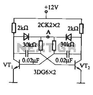
The circuit illustrated in Figure (A) consists of resistors R1 and R2 with values ranging from 15 to 18 kΩ, and capacitors C1 and C2 with capacitance values between 0.01 µF and 10 µF. Figure (B) depicts the oscillation...
Electronics tutorial about the monostable multivibrator circuit, also known as a one-shot monostable multivibrator, used as a pulse generator circuit. The monostable multivibrator is a crucial component in electronic circuits, functioning as a pulse generator that produces a single output...
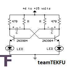
This circuit is an astable multivibrator designed to alternately flash two LEDs. The resistor (R) and capacitor (C) values determine the frequency of the flashing, while the 470-ohm collector load resistors limit the current to approximately 20 milliamps when...
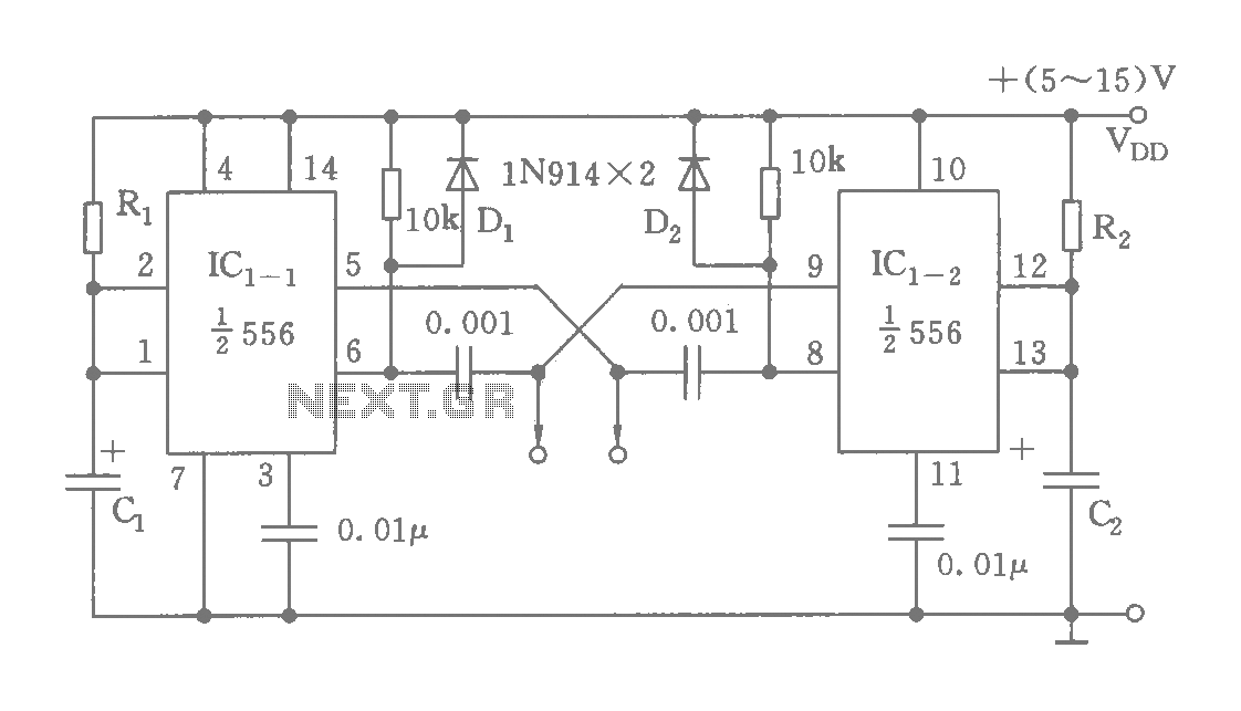
The circuit features a dual time base using a 556 timer, which comprises two synchronized multivibrators and two output clock signals. The output signals are synchronized with defined intervals, and the oscillation frequency can be adjusted by varying the...
Electronics tutorial about the 555 oscillator and how the 555 oscillator can be used as a 555 astable oscillator circuit to generate square wave waveforms. The 555 timer IC is a versatile and widely used component in electronics, particularly for...
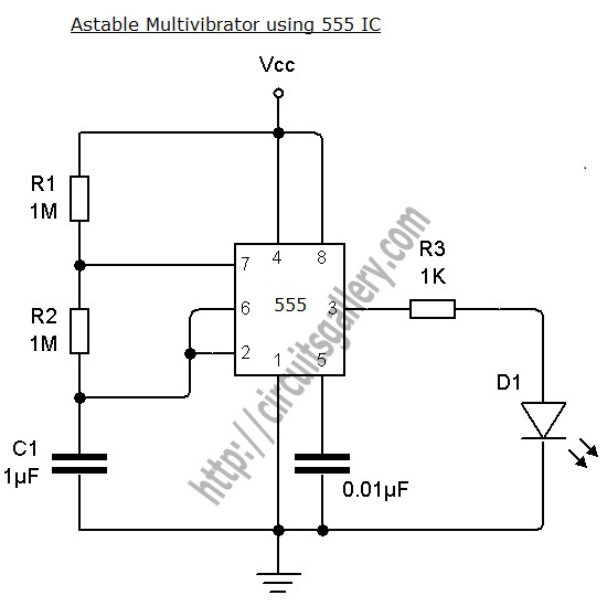
An astable multivibrator can be designed using a 555 timer IC, operational amplifiers, or transistors. The 555 timer IC provides accurate time delays ranging from milliseconds to hours, with the frequency of oscillation adjustable through simple modifications. This is...