
Nathans Z80 Project Mark 2

The schematic design incorporates a 6402 UART as the main communication interface, facilitating serial communication with external devices. The 74HC4060 clock divider generates the necessary clock signals, ensuring that the UART operates at the required baud rate. The crystal oscillator is chosen to provide the specific frequency needed for reliable operation. The MAX232 chip is essential for converting the TTL-level signals from the UART to RS232 levels, making it compatible with traditional serial communication standards. The use of electrolytic capacitors ensures that the voltage levels are appropriately boosted for RS232 signaling.
The tri-state buffer (74LS541) plays a critical role in managing the status signals from the UART. By allowing these signals to drive the data bus, the design ensures that the CPU can effectively monitor UART status without interference. The high impedance state feature of the 6402 is leveraged to maintain continuous signal availability, particularly for the Data Ready flag, which is crucial for interrupt-driven communication.
The jumper configuration for setting the baud rate and UART parameters enhances the flexibility of the design, allowing for easy adjustments based on the application's requirements. This design approach prioritizes simplicity and functionality, ensuring that the UART system operates efficiently while minimizing the need for extensive software configuration. Overall, the schematic represents a robust solution for integrating serial communication capabilities into the existing system architecture.The basic requirement was for some sort of output display and some sort of alpha-numeric input. So the simplest solution I could think of was a UART, attached to something with a screen and keyboard running a serial terminal. I looked at using the PIC already in the system as a UART as well, but decided that it would be better used as a fast DMA c
ontroller with all its pins allocated to that. I had a 6402 UART chip of a similar vintage to the Z80 CPU lying around so that became the core of the UART peripheral. There are three peripheral chips in the UART system, a 74HC4060 clock/divider chip, a MAX232 RS232 level shifter and a 74LS541, an 8 bit tri-state buffer.
The clock/divider chip provides an independent clock source for the UART from the CPU clock. The UART clock has to match the baud-rate so needs to be a fairly weird frequency. The 6402 needs 16 times the baud-rate as an input clock, so I`ve used a 4. 9152MHz crystal. Taking the Q6 (divide by 64) output this gives 4800 baud, the Q5 (divide by 32) output gives 9600 baud and so on. I`ve used a jumper block to allow a baud rate from the range 4800, 9600, 19200 or 38400. The MAX232 chip provides the big voltages needed for "true" RS232 signalling. If you`ve made anything with a serial interface before you`ll probably be familiar with this or a similar chip (e.
g. the MAX202). There`s a bunch of electrolytic caps attached to this to make the suitable voltage step-ups. If you`re using a TTL level USB interface e. g. an FT232 based device, you need to skip the level translator, but I`m planning on plugging this into a real serial port on some old hardware I have. The final peripheral chip is the tri-state buffer. This buffers the status flags from the UART and allows them to drive the data bus when a "status register" is read.
You may notice if you are familiar with the 6402 that there is a pin on the chip that forces the status output pins to enter a high impedance state when driven high. This would of course provide the same function without an external chip. However this also forces the Data Ready flag into a high impedance state, and I wanted to make this into an interrupt input to the Z80, which would mean all the status pins would have to be driving continuously, hence the extra buffer.
This means that the Data Ready flag, which occurs when a new byte has been received can interrupt the CPU. You may notice looking at the circuit diagram that the register names are familiar if you have used the PIC UART before, that`s because I have used it a lot and found the 6402 very closely fits the PIC`s UART design, and so used those familiar names in my design.
I haven`t attempted to match the bit pattern in the status register or anything though, so don`t assume that they really are the same. The config bits for the UART (e. g. parity type, number of stop bits etc. ) I have set with a row of jumpers wired with pull-up resistors that are shorted to ground if you fit the jumper.
I considered making them into another register along with the baud rate select, but the additional chips would have take a lot of space and wiring, and I can`t see that the system is likely to need to software configure the serial port when it is the primary input/output device. 🔗 External reference
Related Circuits
Cemetech's hardware and software projects, including web applications, books, and DIY hardware modifications. Cemetech encompasses a diverse range of projects within the realms of hardware and software. The initiative includes the development of web applications designed to enhance user interaction...
This digital dice electronic project utilizes a combination of a 555 timer, a 7490 decade counter, a 7483 4-bit binary adder, a 7447 BCD to 7-segment decoder, and a 7-segment display to show the digit. The digital dice project is...
When the start button is pressed, the Arduino selects a random 4-digit code and flashes lights to indicate the code. If the user successfully repeats the code using the other buttons, the XBee module sends a message to another...
The DC motor drive controller can control two DC motors of varying current or voltage ratings, depending on the relay specifications. The circuit includes two shaft encoders that provide positional feedback to a computer. The motor control circuit connects...

This stereo balance indicator circuit diagram is designed using a few common external components. The schematic circuit is simple to build and provides a visual indication with LEDs for left, right, and center balance. Outputs from each channel are...
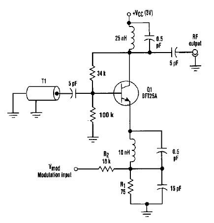
This varactorless high-frequency modulator electronic project must be powered by a simple DC 3-volt power source, such as a 3-volt battery. Traditionally, high-frequency oscillators are frequency-modulated using a varactor. However, varactors typically require a significant voltage change to achieve...