
Ni-Cd battery charger circuit

The circuit operates by utilizing a power supply that provides the necessary voltage and current for charging the batteries. The main components typically include a transformer, a bridge rectifier, a filtering capacitor, and a voltage regulator, along with necessary protection diodes and resistors.
The transformer steps down the AC voltage from the mains supply to a level suitable for charging the batteries. The bridge rectifier converts the AC voltage to DC, which is essential for battery charging. The filtering capacitor smooths out the rectified DC voltage, reducing ripple and providing a more stable output.
For charging 12V Ni-Cd batteries, the circuit ensures that the voltage across the battery terminals does not exceed the maximum charging voltage of approximately 14.4V. This is crucial to prevent overcharging, which can lead to battery damage. The voltage regulator can be adjusted to provide the appropriate output voltage for 6V and 9V battery packs, ensuring compatibility with different battery configurations.
Additionally, incorporating a charging indicator LED can provide visual feedback on the charging status. A current limiting resistor may also be included to prevent excessive current flow during the initial charging phase, which can be particularly important for older or partially discharged batteries.
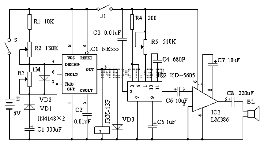
Overall, this circuit offers versatility in charging various Ni-Cd battery packs, with the potential for further enhancements to improve efficiency and safety during the charging process.This circuit can be primarily used for charging 12V Ni-Cd battery packs. Any way 6V and 9V battery packs can be also charged by using this circuit a little.. 🔗 External reference
Related Circuits
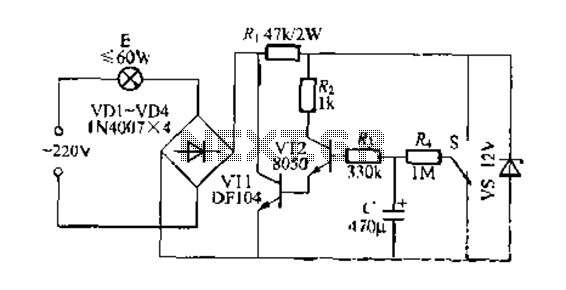
This circuit is a gradual clear/fade switch for a two-wire connection, designed for simple installation. It activates the lights as needed by turning the switch dial upward. A positive supply of 2V is provided through resistor R. The capacitor...
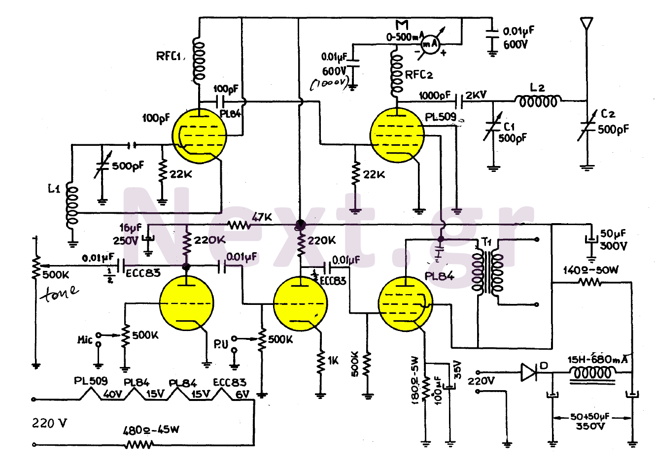
The simplicity of this transmitter, combined with its high performance, makes it particularly interesting. It has an output power of approximately 30 W, and under normal conditions, with the appropriate antenna and handling, it can achieve a range of...
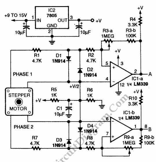
The circuit illustrated in the schematic diagram below allows for the visualization of the direction and shaft rotation of a stepper motor on an LED display. Instead of utilizing a digital rotation encoder as an input, this circuit employs...
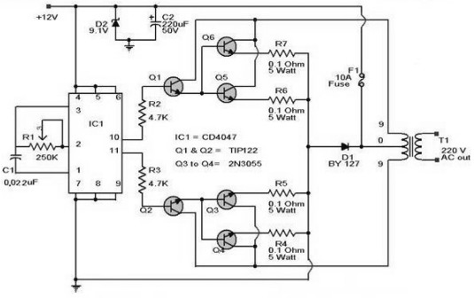
A 12 V car battery can be utilized as the 12 V input power source. The potentiometer R1 can be adjusted to achieve a 50 Hz output frequency. It is recommended to use a 10 A fuse in series...
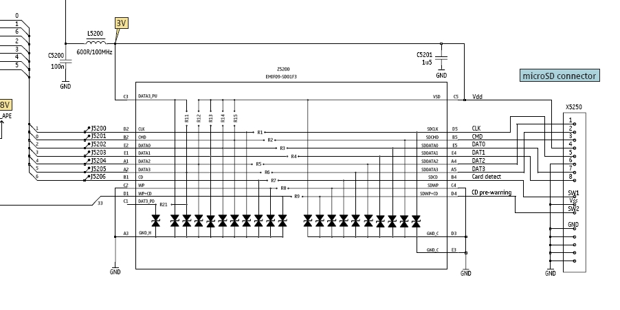
In this tutorial, the functioning of the memory card circuit in mobile phones will be explored. The previous post discussed the pin-outs and types of memory cards utilized in cellular devices. The accompanying block diagram illustrates how the removable...
Cats are natural predators of rats, and the use of electronic devices to simulate meowing sounds as a repellent is an effective method. These electronic devices can produce meowing sounds at various frequencies and intervals, making them suitable for...