
One-IC two-tones Sirens

The circuit operates primarily on the principles of audio signal generation and modulation, making use of integrated circuits (ICs) for sound synthesis. SW1 serves as a toggle switch, allowing the user to select between two distinct audio outputs. The first output, produced in the police/fire brigade mode, relies on the simultaneous oscillation of IC1A and IC1B, which creates a dual-tone effect. This is particularly effective for mimicking emergency vehicle sounds that capture attention.
In contrast, the second output mode, activated by the alternate position of SW1, utilizes IC1C and IC1D to create a siren sound that modulates in frequency. The behavior of the siren sound is characterized by a rapid increase in pitch followed by a gradual decrease, simulating the sound of traditional emergency sirens.
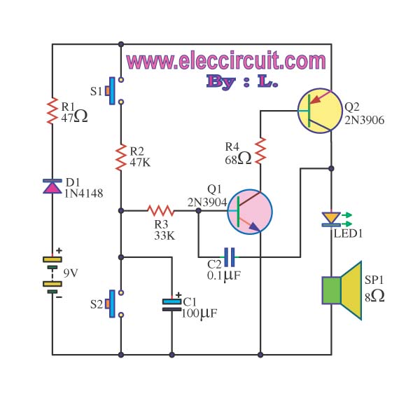
The circuit's loudspeaker, driven by Q1, must be selected with care to ensure adequate sound output quality. It is recommended to use a speaker that is both appropriately sized for the application and housed in a casing that enhances sound projection. This will help in achieving a more immersive auditory experience.
Furthermore, the flexibility to adjust the sound characteristics is facilitated through the capacitors (C1, C2, C5, C6) and associated resistors. By altering these components, one can fine-tune the frequency response and duration of the sound waves generated by the circuit, allowing for customization based on user preference or specific application requirements.
The absence of a power switch simplifies the circuit design while maintaining efficiency. By keeping SW1 in the low position, the circuit minimizes power consumption, making it suitable for battery-operated devices without significantly draining the power source. This design consideration is particularly important for portable applications where battery life is a critical factor.This circuit is intended for children fun, and is suitable to be installed on bicycles, battery powered cars and motorcycles, but also in models and other games. With SW1 positioned as shown in the circuit diagram it reproduces the typical dual tone sound of Police or Fire-brigade cars, by the oscillation of IC1A and IC1B gates.
With SW1 in the ot her position, the old siren sound increasing in frequency and then slowly decreasing is reproduced, by pushing on P1 that starts oscillation in IC1C and IC1D. The loudspeaker, driven by Q1, should be of reasonable dimensions and well encased, in order to obtain a more realistic and louder output.
Tone and period of the sound oscillations can be varied changing the values of C1, C2, C5, C6 and/or associated resistors. There is no power switch: leave SW1 in the low position (old-type siren) and the circuit consumption will be negligible.
🔗 External reference
Related Circuits
The siren circuit plays a crucial role in various alarm systems, including emergency alerts, burglar alarms, fire alarm circuits, timers, and sensor controls. Without these circuits, it would be impossible to recognize the intended functionality. The operation of the...

This circuit produces a siren-like sound similar to that of ambulance sirens. Unlike traditional ambulance siren circuits that typically use an IC 555, this design employs transistors, making it more economical and easier to customize. The operation of the...

The operation of the circuit is divided into three parts: low-frequency production, high-frequency manufacturing, and low-frequency extension. The low-frequency signal is generated from IC1, which is connected to an astable multivibrator circuit. The frequency is determined by the resistor...

The circuit operates using a UM3516 integrated circuit (IC1), which is designed to generate sound. The output sound is produced at pins 7 and 8 of IC1, and the components R1 and VR1 are utilized to control the frequency...
This circuit generates a sound similar to that of ambulance sirens. It differs from typical ambulance siren circuits in its design. The circuit utilizes a combination of oscillators and amplifiers to produce a sound that mimics the varying pitch and...
This circuit is designed for children's entertainment and is suitable for installation on bicycles, battery-powered cars, and motorcycles, as well as in models and other games. When switch SW1 is positioned as indicated in the circuit diagram, it reproduces...