
One of the high-pressure sensing alarm circuit

The described circuit employs a 555 timer IC in a non-stable multivibrator configuration to create an audio alert system responsive to specific electric fields. The circuit is designed to monitor the proximity of high-voltage sources and generate audible signals through a piezoelectric transducer.
In this configuration, the 555 timer operates continuously in a state of oscillation, producing a square wave output. The frequency of oscillation can be adjusted by changing the resistor and capacitor values connected to the 555 timer. The output from the timer is fed into a piezoelectric ceramic sheet, which converts the electrical signals into sound.
When the sensor is activated by detecting a high-voltage electrified body, the output of the 555 timer changes, triggering the piezoelectric element to emit a loud alarm sound. This serves as an immediate warning signal.
In addition, the circuit is sensitive to varying electric fields. When the sensor detects a high-frequency electric field, the output frequency of the 555 timer increases, causing the piezoelectric element to produce a vibrating sound. Conversely, when the sensor is near an electrostatic field, the output alters to create a sound that resembles a flute, adding a distinct tonal quality to the alarm system.
Overall, this circuit design effectively combines the functionalities of proximity sensing and sound generation, providing a versatile alert mechanism for high-voltage environments.By the 555 IC A composed of a non-steady-state self-excited multivibrator. When the sensor very close to the high-voltage electrified body, the piezoelectric ceramic sheet B out alarm. When it is close to the frequency electric field, cricket issue vibrato; close when the electrostatic field, emit electrical flute-like sound straight.
Related Circuits
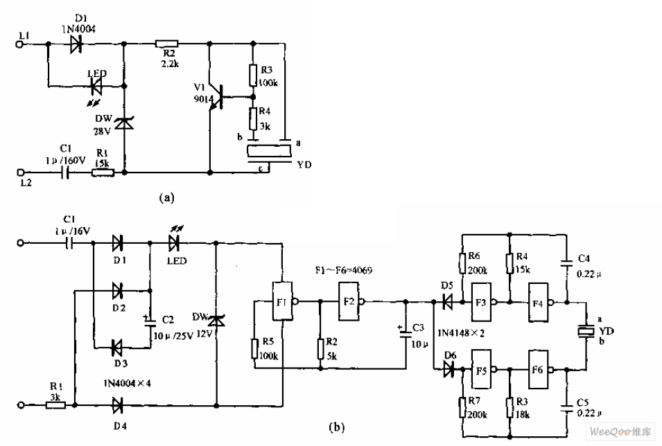
The telephone electronic ringer circuit is illustrated in the provided figure. It features an NPN transistor (either 9014 or 3DG12) as the primary component. The sound device, referred to as YD, functions as both a feedback device and is...
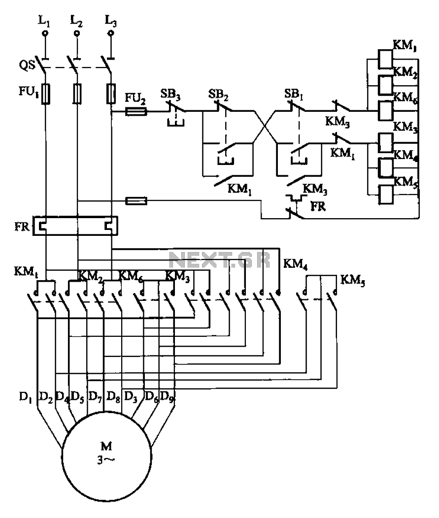
The circuit illustrated in Figure 3-107 features a low-speed operation button (SBi) and a high-speed operation button (SB2). The circuit design depicted in Figure 3-107 integrates two operational modes controlled by distinct buttons: SBi for low-speed operation and SB2 for...
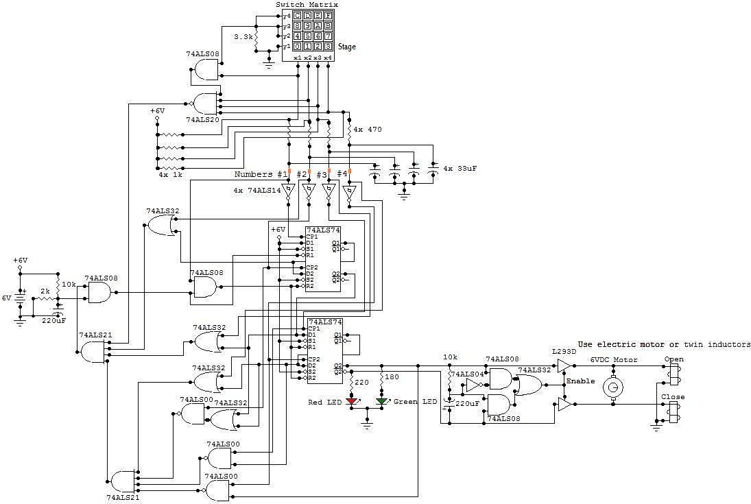
This circuit is an electronic locker controlled by a combination of switches (a code). It features a switch matrix located on the locker door, consisting of a unit of switches arranged in four rows and four columns, totaling eight...

This circuit diagram of a UPS is designed for use with cordless telephones that cannot operate during a power failure. Since the UPS is intended solely for telephones, its output power is limited to 1.5W. This UPS circuit is...
The circuit for automatic brightness adjustment in a television utilizes a photosensitive resistor and a contrast potentiometer connected to an intermediate stage. The photosensitive resistor varies its resistance based on light intensity, causing changes in the potential at the...
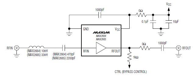
A simple, low-cost, and ultra-compact VHF/UHF low-noise amplifier circuit can be designed using the MAX2664 and MAX2665 ultra-compact LNAs for VHF/UHF applications. These devices incorporate a broadband LNA with an integrated bypass switch. The MAX2664 covers the UHF frequency...