
one second audible clock

The described circuit serves as a timing mechanism, providing a one-second output signal through auditory and visual indicators. The primary component, the CMOS 4024 counter/divider chip, is capable of counting and dividing frequencies, making it ideal for applications that require precise timing intervals. The high input impedance at pin #1 facilitates easy signal input, allowing for straightforward activation by simply touching the pin or using a wire.
In practical implementation, the circuit can be powered by a range of battery voltages, although careful consideration must be given to the resistor values, particularly R3, to ensure proper functionality across different voltage levels. The optional visual display, formed by the LED (D4) and resistor (R3), enhances user interaction by providing a visual cue in addition to the audible beep or click.
The modifications for 60Hz operation involve critical changes to the diode connections, ensuring that the circuit remains functional in environments where the mains frequency differs from the standard 50Hz. This adaptability allows the circuit to be utilized in various geographical locations without compromising performance.
Overall, this circuit design is versatile and can be easily modified to suit specific requirements, making it suitable for applications ranging from educational tools to industrial timing solutions.A beep or metronome-like click and/or a visible flash, will beat the one-second time and can be useful in many applications in which some sort of time-delay counting in seconds is desirable. The circuit is formed by a CMos 4024 counter/divider chip and 3 diodes, arranged to divide the frequency of the input signal at pin #1 by 50 (or 60, see Notes
). The input impedance at pin #1 is very hight, so simply touching the pin (or a short track or piece of wire connected to it) is usually enough to provide the necessary input signal. Another way to provide an input signal consists in a piece of wire wrapped several times around any convenient mains cable or transformer.
No other connection is necessary. To allow precise circuit operation in places where the mains supply frequency is rated at 60Hz, the circuit must be modified as follows: disconnect the Cathode of D1 from pin #11 of IC1 and connect it to pin #9. Add a further 1N4148 diode, connecting its Anode to R1 and the Cathode to pin #6 of IC1: that`s all! The visual display, formed by D4 and R3 is optional. Please note that R3 value shown in the Parts list is suited to low battery voltages. If 9V or higher voltages are used, change its value to 1K. 🔗 External reference
Related Circuits
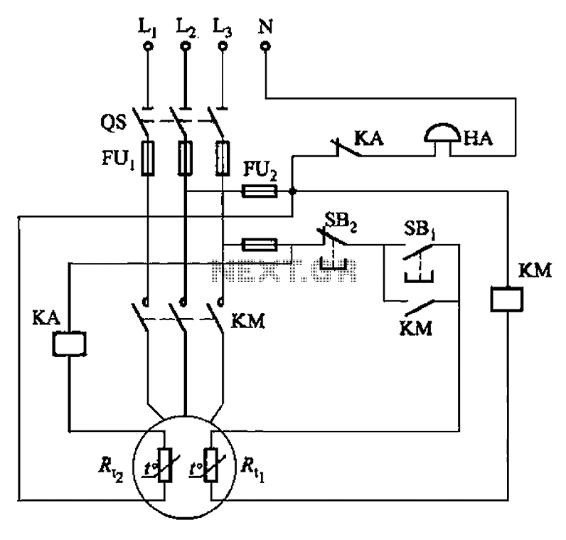
The circuit illustrated in Figure 4-2 employs two thermal resistors. One, designated as Rc, functions as overload protection, while the other, labeled Rt, serves as an alarm. The circuit in question integrates two thermal resistors to monitor temperature changes and...
This circuit consists of a 6 Zone Alarm system with an LED display. The alarm system features 6 independent zones and includes a 7-segment LED display, along with one timed entry/exit zone. The 6 Zone Alarm system is designed to...
The second-order multipurpose filter described here can function as a low-pass, bandpass, high-pass, or notch filter at audio frequencies. Its unique feature is the ability to independently vary all characteristics using potentiometers. In basic filters, only one k value...
The above shows a home-built digital clock that utilizes Nixie tubes for display. Unlike most contemporary Nixie clocks, this design does not employ transistors or integrated circuits for driving the tubes. Instead, the driving logic is constructed using neon...
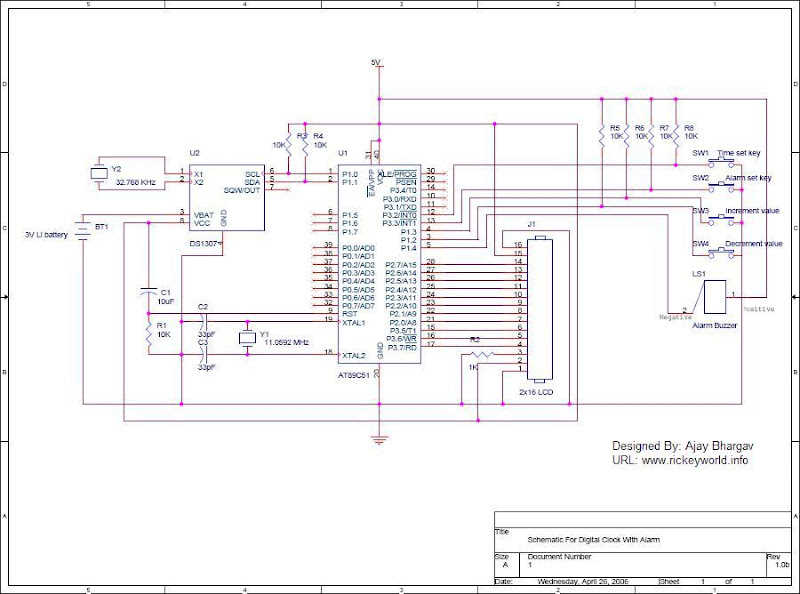
After the SCL line is high, the SDA line must be held low to indicate that the data being transmitted is legally binding. The data can only change when the SCL line is low. During the transfer of a...
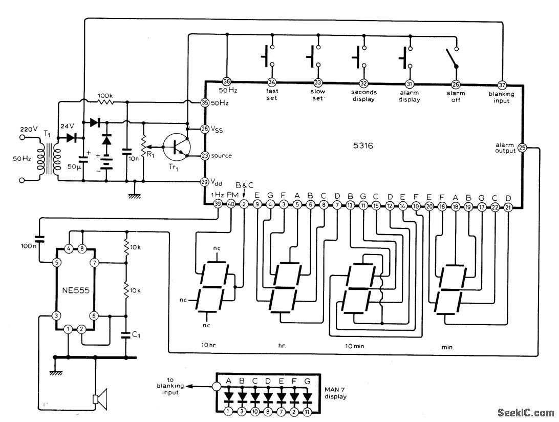
The circuit utilizes the MM5316 alarm-clock integrated circuit (IC), which is originally intended for driving LCD or fluorescent displays. In this implementation, it has been adapted for use with LED display diodes. The system is designed to operate on...