
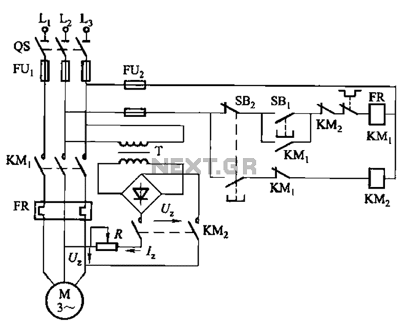
One-way operation of a dynamic braking circuit
The 3133 circuit design incorporates a dynamic braking system that is essential for applications where rapid deceleration of motors is required. The circuit operates by converting the kinetic energy of the motor into electrical energy, which is then dissipated as heat in a resistive load.
The dynamic braking system is controlled manually through a set of buttons, allowing operators to engage or disengage the braking process as needed. This feature is particularly useful in scenarios where immediate stopping is necessary, such as in conveyor systems or industrial machinery.
The power supply for the dynamic braking circuit is derived from a step-down transformer, which reduces the AC voltage to a level suitable for the rectification process. The rectifier bridge converts the AC voltage to DC, providing a stable power source for the braking system. The inclusion of diodes in the circuit ensures that current flows in the correct direction, allowing for effective energy conversion during the braking phase.
Furthermore, the circuit's design is optimized for motors rated up to 7.5 kW, making it a reliable choice for medium-sized applications. For larger motors, it is advisable to implement a three-phase rectifier circuit to handle the increased power demands efficiently. This adaptation ensures that the braking system remains effective and responsive, even under high-load conditions.
Overall, the 3133 circuit exemplifies a practical approach to dynamic braking in electric motor applications, combining manual control with robust electrical components to achieve effective deceleration and energy management.3133 circuit shown in FIG. Figure 3-133 (a), dynamic braking (b), (c) the three lines by manually (button) control. Wherein FIG. (A), (b) the dynamic braking DC power supply wi th step-down transformer, rectifier bridge rectifier obtained, FIG. (C) The current power dynamic braking win by a diode obtained similar they work, but the former than the latter braking effect is good. This circuit, commonly used in the following 7. 5kW, braking demanding situations. For larger power motors, brake should be used with DC power three-phase rectifier circuit.
Related Circuits

Intercom walkie-talkies represent an advanced application of crystal oscillators for voice transmission. Utilizing a crystal-locked oscillator for voice transmission is complex due to the oscillator's fixed frequency, which is challenging to modulate. The primary method for achieving this involves...
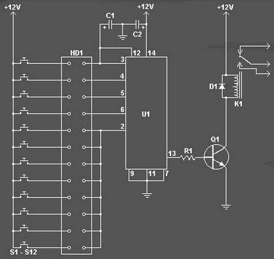
The Digital Combination Lock Circuit is a schematic for a simple electronic combination lock utilizing the LS7220 integrated circuit (IC). This password-protected digital lock can activate a relay to control any device by entering a preset combination of four...
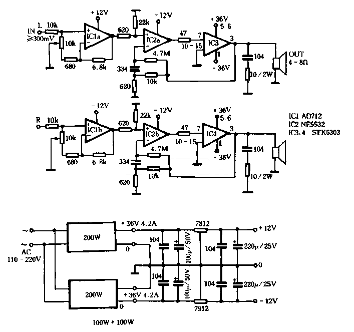
The T amplifier circuit schematic section is illustrated in Figure 3-51. It utilizes the Japan Sanyo STK6303 Pina, which is a high-power thick film integrated circuit. The maximum power supply voltage is 36V, and the output current can reach...
The following circuit illustrates a timer circuit with independent mark and space periods. It is based on the 7555 integrated circuit (IC). The high output duration is calculated by T(on) = 0.7 Ra Ct, while the low output duration...
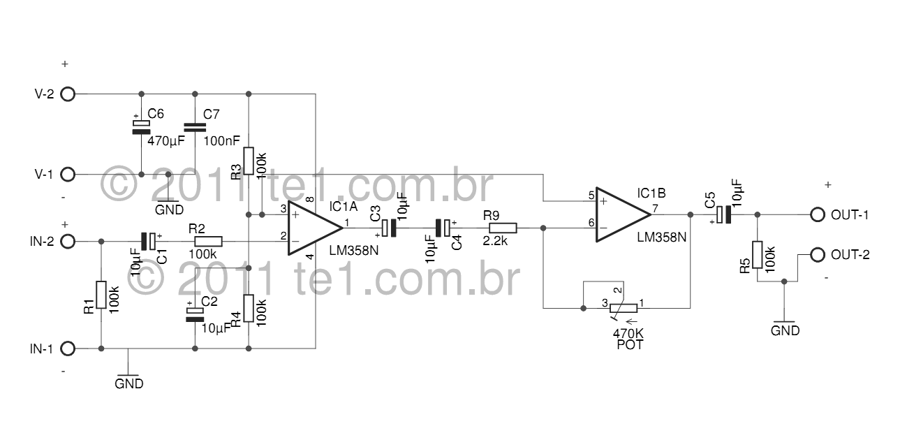
The LM358 series consists of two independent, high-gain, internally frequency-compensated operational amplifiers designed specifically to operate from a single power supply over a wide range of voltages. Operation from split power supplies is also possible, and the low power...
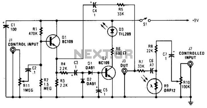
In this circuit, audio input to the control channel is amplified and rectified by diodes D1 and D2. This direct current level activates LED D3 through transistor Q2. The illumination from LED D3 causes R9, a light-dependent resistor, to...