
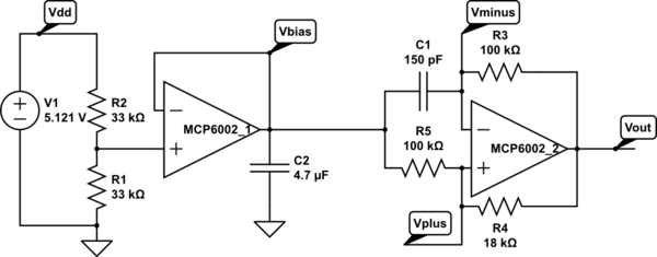
op amp Flow of current in a simple inverting amplifier circuit

In this scenario, the circuit consists of a voltage source connected to a resistor R1, which is then linked to an ideal op-amp. The op-amp is configured in a non-inverting or inverting configuration, depending on the specific application. The ideal characteristics of the op-amp imply that it has infinite input impedance, resulting in no current entering the input terminals. Consequently, the current flowing through R1 must adhere to Kirchhoff's current law, which states that the sum of currents entering a junction must equal the sum of currents leaving that junction.
When the voltage source transitions from 0V to 1V, a potential difference is established across R1. The current through R1 can be calculated using Ohm's law, where I = V/R, with V being the voltage across R1 and R being the resistance. Given that the op-amp inputs do not draw current, the current flowing through R1 will either flow to the output of the op-amp or through any feedback network connected to the output, depending on the configuration.
For practical applications, it is crucial to consider the limitations of real op-amps and voltmeters, as they do draw some current. This could lead to discrepancies in the behavior of the circuit when transitioning from theoretical assumptions to actual hardware implementation. Understanding these nuances is vital for engineers and designers when developing circuits that utilize op-amps and other components, ensuring that all elements are appropriately accounted for to maintain circuit integrity and performance.Considering a simple circuit like the one below. Let us say that the voltage source suddenly turns on (from 0V to 1V), then current will through through the resistor R1, correct But assuming an ideal op-amp (drawing no current) and an ideal voltmeter (drawing no current), where does the current flow to (in order to satisfy Kirchhoff`s curren t law) If you read "correctly powered" into "assuming an ideal opamp", I have to withdraw my critical comment; I just thought it`s worth pointing out the issue in case the questioner later goes on to build real hardware. 🔗 External reference
Related Circuits
A touch sensor relaxation oscillator is utilized in the hysteresis lab. In this schematic, the variable capacitor is represented by a person's finger and a touch plate made from aluminum foil and packing tape. Code was developed for the...
This document outlines a straightforward process to transmit voice over a distance using amplitude modulation of light through sound vibrations. It details how modulated light is detected and demodulated by a receiver to reproduce sound. The experiments described are...
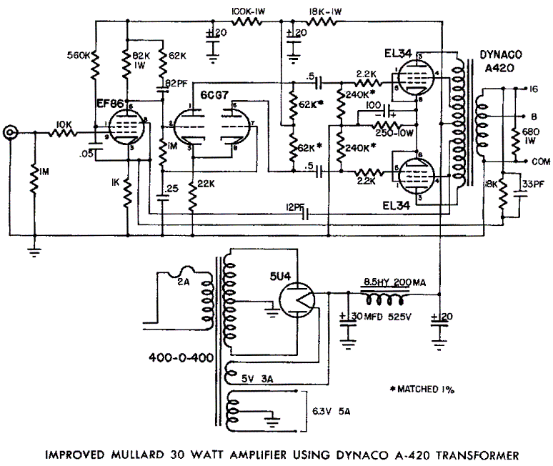
Mullard EL34 push-pull vacuum tube amplifier schematic using Dynaco A420 audio output transformers The Mullard EL34 push-pull vacuum tube amplifier is a classic audio amplification circuit that utilizes EL34 vacuum tubes in a push-pull configuration to deliver high-quality sound reproduction....
This circuit is designed to work at UHF frequencies in the range 450-800MHz. It has a gain of around 10dB and is suitable for boosting weak TV signals. The circuit is shown below. The described circuit operates within the Ultra...
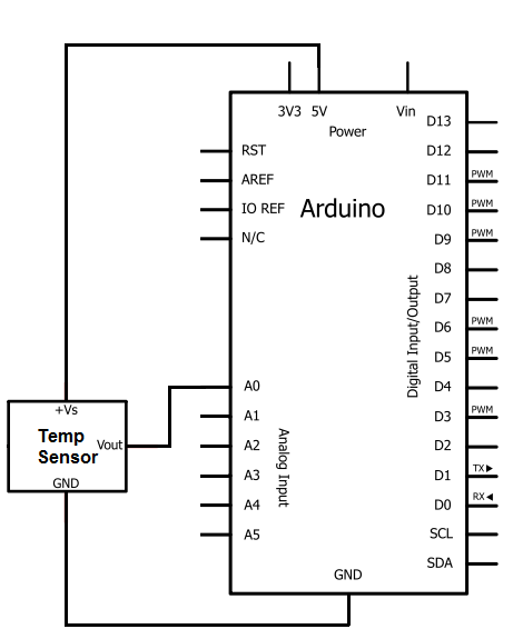
The integrated circuit (IC) used for temperature measurement is the TMP36. This IC will be integrated with an Arduino to obtain temperature readings. The Arduino will read the measured value from the TMP36 and convert it into degrees Fahrenheit,...
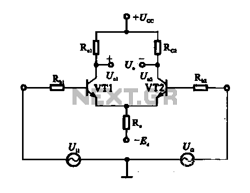
An emitter-coupled differential amplifier circuit is designed to suppress zero drift through circuit symmetry. The effectiveness of zero drift suppression improves with better symmetry; however, in practice, achieving complete symmetry is not feasible. Consequently, the basic differential amplifier circuit...