
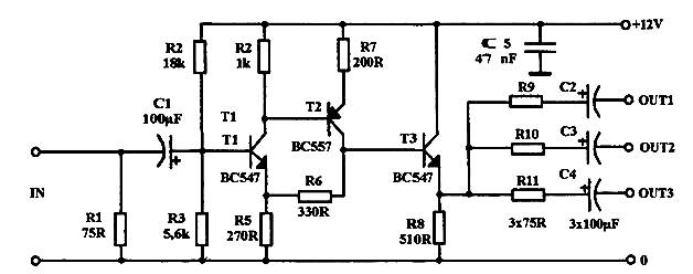
DC to 100W amplifier circuit diagram of 500KHZ
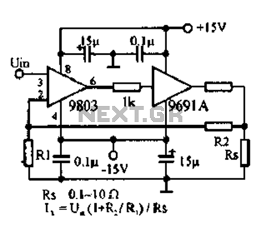
The described amplifier circuit employs a photoelectric starting operational amplifier, which is essential for achieving high input impedance and gain. This characteristic is particularly beneficial for applications requiring minimal signal distortion, such as in high-fidelity audio systems. The operational amplifier's design allows for transformerless output, which simplifies the circuit architecture and enhances efficiency by eliminating the need for bulky transformers that can introduce additional noise and signal loss.
The amplifier is capable of delivering up to 100W of output power, with a load current capacity of 10A. This necessitates careful consideration of the wiring layout to ensure it can handle the high current without overheating or introducing resistive losses. The use of appropriate gauge wires is critical to maintaining performance and reliability in high-power applications.
To support the high current demands, the circuit requires the inclusion of power supply bypass capacitors. These capacitors serve to stabilize the power supply, reducing voltage fluctuations and ensuring that the amplifier operates smoothly under varying load conditions. The selection of bypass capacitors should be made based on their voltage rating and capacitance value to effectively filter out noise and provide a stable power source.
In addition to audio applications, this amplifier circuit can be utilized in cathode-ray deflection systems, where precise control of electron beams is necessary for image rendering. The high gain characteristics of the operational amplifier allow for fine adjustments in beam positioning, contributing to improved image quality.
Furthermore, in servo systems, the amplifier's ability to provide substantial output power and precise control can be leveraged for applications such as motor control and positioning systems. The design's versatility makes it suitable for various applications that demand high performance and reliability in signal amplification.DC to 500KHz of 100W amplifier photoelectric starting op amp high input impedance, high gain characteristics, to achieve transformerless output power 100W. Load current up to 1 0A, the wiring requirements for high current and high power supply bypass capacitors. This circuit is used for high-fidelity audio circuits, cathode-ray deflection and a servo system.
Related Circuits
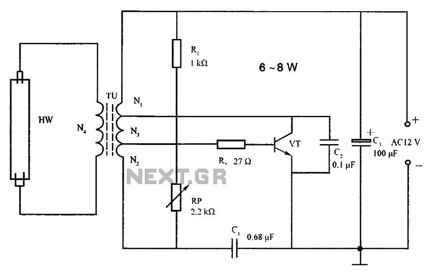
The lighting inverter circuit is designed for 6 to 8W fluorescent tubes. This circuit is appropriate for powering fluorescent tube circuits within the specified wattage. The parameters for the circuit are indicated in the accompanying figure. When utilizing a...
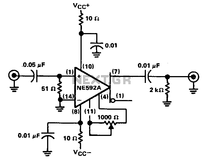
The circuit provides a voltage gain of 20 ±0.1 dB within a frequency range of 500 kHz to 50 MHz. The low-frequency response of the amplifier can be enhanced by increasing the value of the 0.05 µF capacitor connected...
This circuit functions with inaudible (ultrasonic) sound. Sound of frequency up to 20 kHz is audible to human beings. The sound of frequency above 20 kHz is called ultrasonic sound. The circuit described generates (transmits) ultrasonic sound of frequency...
The WSH412 is designed to integrate a Hall sensor with complementary output drivers and a frequency generator on a single chip. It is suitable for applications such as speed measurement, revolution counting, positioning, and DC brushless motors. The device...
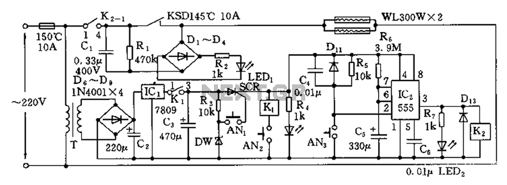
The disinfection cabinet circuit operates on the principle of using infrared heating within a closed cabinet to create a high-temperature environment for disinfecting tableware. The circuit includes an AC buck regulator, an infrared heating circuit, and a timing control...
Video power amplifier circuit diagram. The circuit operates exclusively with AV compounds, where video and audio signals are transmitted separately. It is not suitable for connections involving "HF" antenna cables. Ensure that the video amplifier is included in the...