
BT9404 type excitation switch control circuit
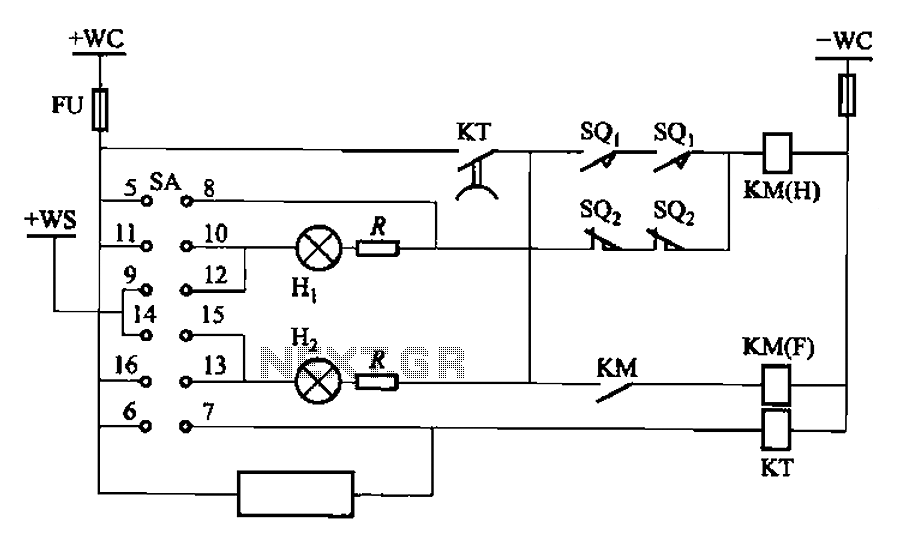
The BT9404 de-excitation type switch is designed to effectively manage the operation of CJ4-S contactors and JT3-21/3 electromagnetic relays in various electrical applications. The schematic representation of the control circuit, as illustrated in Figure 7-55, provides a comprehensive overview of the interconnections and functionalities of the components involved.
The CJ4-S contactors serve as the primary switching devices, responsible for controlling high-power circuits. They are designed to handle significant load currents and voltages, ensuring reliable operation in demanding environments. The JT3-21/3 time relay introduces a delay function, allowing for precise timing control in the switching operation. This feature is crucial in applications where sequential operation or time-based control is required.
The SA component plays a vital role in controlling the LW2-2-la switch, which is responsible for managing multiple outputs, indicated by the numbers 4, 6a, 40, and 20/F8. This switch configuration allows for flexible control over various circuits, enhancing the overall functionality of the system.
The inclusion of Hi and Hz indicators in green and red provides visual feedback on the operational status of the system, facilitating monitoring and diagnostics. The specifications of 11OV and 8W indicate the operational voltage and power consumption of the indicators, ensuring they are suitable for integration into the control circuit without overloading.
Furthermore, the additional resistance of 2.5kΩ is likely employed for current limiting or signal conditioning purposes, ensuring that the control signals remain within acceptable levels for the connected components. The SQ1 and SQ2 terminal switches are crucial for establishing connections within the circuit, allowing for the integration of external devices and enhancing the modularity of the system.
Overall, the BT9404 de-excitation switch, in conjunction with CJ4-S contactors and JT3-21/3 relays, forms a robust control circuit capable of managing complex electrical tasks with precision and reliability. BT9404 de-excitation type switch by the CJ4-S contactors and JT3-21/3-type electromagnetic relays. Its control circuit is shown in Figure 7-55. Figure, KM contactors CJ4-S; KT was time relay JT3-21/3; SA controls switch LW2-2-la, 4, 6a, 40, 20/F8; Hi, Hz green, red XD2, llov, 8W, additional resistance 2.5k0; SQi, SQ2 for the terminal switch.
Related Circuits
There are two independent modeling light circuits for the P2000D, one for each of the two channels. The modeling light circuit is completely separate from the high voltage strobe circuitry, even featuring its own On/Off switch. Therefore, the functionality...
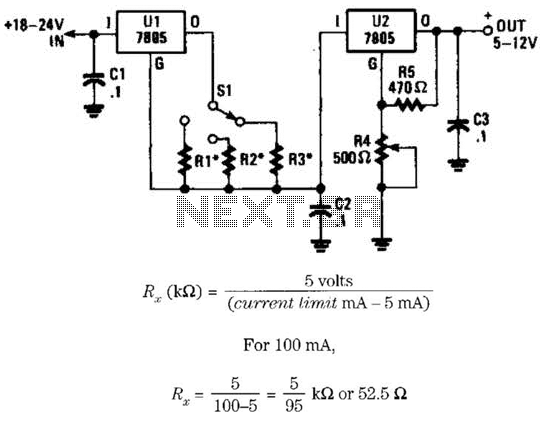
This voltage regulator and current limiter combination can be constructed using two 7805 regulators as illustrated. Resistors R1, R2, and R3 should be chosen to achieve a 5-V drop at the maximum allowable current limit. Switch S1 selects one...
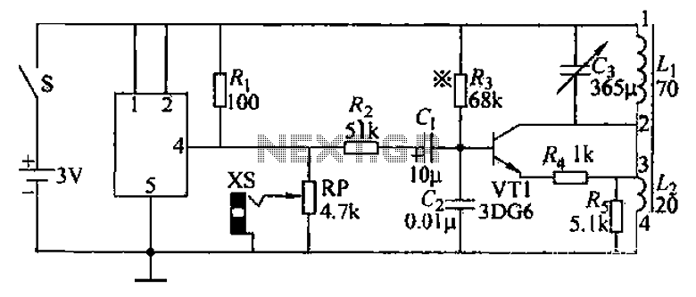
An audio frequency signal generator can output audio signals, 465 kHz spectral amplitude signals, and 52.5 Hz to 16 kHz high-frequency amplitude-modulated signals. The high-frequency oscillator's vibration frequency is determined by the components G and L. A variety of...
The AM transmitter circuit consists of an audio amplifier and an RF oscillator. The oscillator is constructed around transistor Q1 and its associated components. The tank circuit, which includes inductor L1 and variable capacitor VC1, is tunable from approximately...
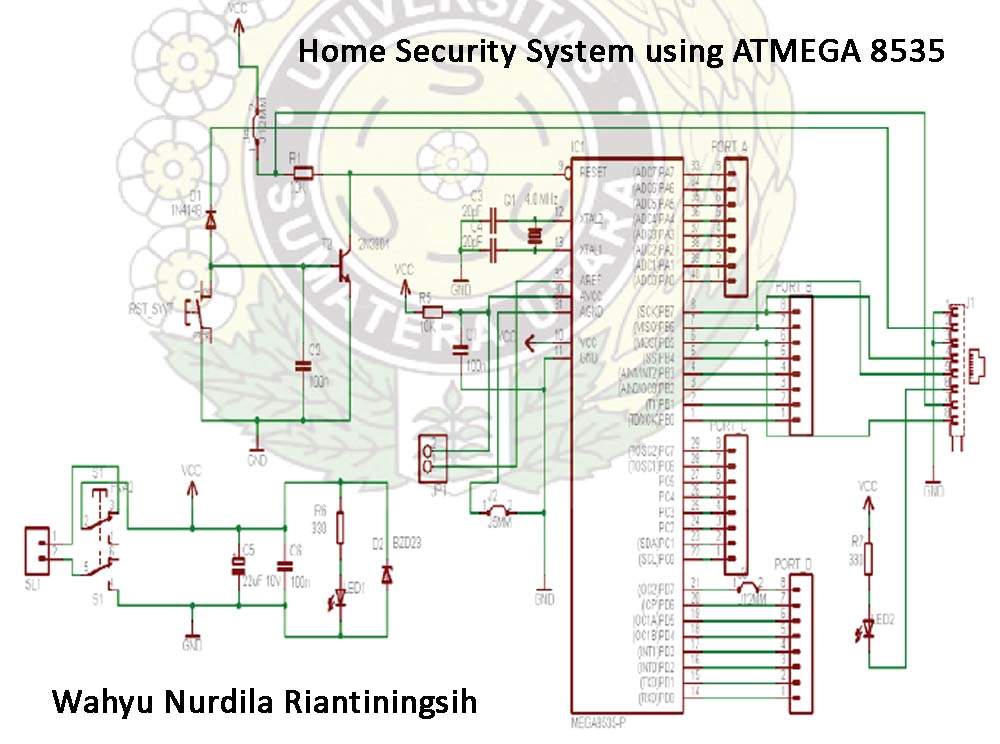
The Atmega 8535 Color Conversion to Frequency project utilizes instrumentation technology to recognize colors, also known as a color sensor, which is essential in various industrial applications. This sensor has multiple uses, ranging from the paint industry to satellite...
The schematic shown below is a 555 timer circuit. The NE555 is a well-known integrated circuit that comes in an 8-pin dual in-line package (DIP). There is a vast array of circuits utilizing the 555 IC, which contributes to...