
Overvoltage Protection Circuit Circuit

The described circuit serves as a protective mechanism during the testing of electronic components or circuits. The design incorporates a variable voltage source, which allows for flexibility in testing various devices under different voltage conditions. The inclusion of overvoltage protection is critical, as it safeguards sensitive components from damage due to excessive voltage levels.
Resistor R1 plays a pivotal role in establishing a safe operating range. By adjusting R1 to a value slightly below the shutdown threshold, the circuit ensures that it remains operational until the critical voltage limit is approached. This proactive approach to voltage management allows for accurate testing while preventing accidental overvoltage scenarios.
Resistor R2 is integral to defining the trip voltage, which is the specific voltage level at which the shutdown mechanism activates. The precise calibration of R2 is essential for the reliability of the circuit, as it determines the threshold that triggers the protective shutdown.
When the voltage across R2 reaches the predetermined trip point, the circuit activates a shutdown feature that disconnects the power supply to the circuit under test. This immediate response serves to protect the tested device from potential damage caused by overvoltage conditions.
To restore functionality after a shutdown event, the user must first lower the resistance of R1 to a level below the trip threshold. This adjustment allows the circuit to reset and prepares it for subsequent testing. The activation of the reset switch S1 is a crucial step in this process, as it clears the shutdown state and re-establishes the connection to the voltage source.
Overall, this circuit design emphasizes safety and adaptability in electronic testing environments, making it an invaluable tool for engineers and technicians working with sensitive electronic components. The combination of adjustable resistors and a reset mechanism provides a comprehensive solution for managing voltage levels effectively. When testing a circuit, a source of voltage that is variable and has overvoltage shutdown is veiy useful. In this circuit, Rl is adjusted to 1 to 2 V below the eventual shutdown threshold. R2 sets the trip voltage. When this voltage is reached, the circuit shuts the voltage to the circuit under test down. To reset, reduce Rl belowtrip threshold and depress reset switch SI.
Related Circuits
This circuit automatically controls the headlight of a motorcycle, turning it on and off independently of the light and ignition switches, as long as the battery is fully charged. The initial stage employs a 220-ohm resistor and ZD1 to...
This circuit describes a simple 6-bit random number pseudo-generator used to study binary counters and, in particular, shift registers. Some basic background information about binary counters and shift registers is provided. In reality, there are dozens of different shift...
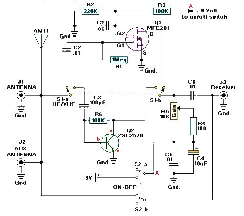
A simple and efficient active antenna electronic project can be designed using this electronic schematic circuit based on transistors. This active antenna project is effective for a wide range of RF frequencies, covering three RF bands: HF, VHF, and...
This is an add-on Over Voltage Circuit for the LM317 Regulator Circuit submitted by Matthew Hewson. It is a voltage regulator that allows a 6v portable supply to be derived from the 12v car battery. You can add a...
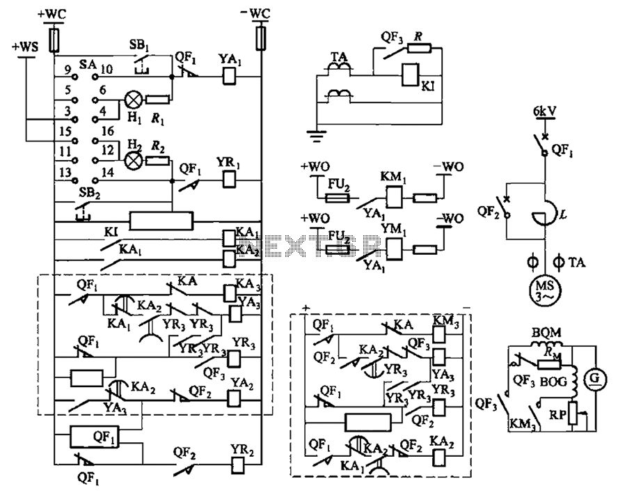
The circuit depicted in Figure 3-189 includes various components such as switch SA, closing button SBi, trip button SBz, de-excitation switch Yaa, and off trip coil YR3. The excitation switch contacts are represented by QF3, which serves as a...
The circuit consists of two synchronized multivibrators formed by a pair of 555 timer circuits. It is capable of generating two synchronized pulse signals, with the spacing and frequency adjustable by modifying the time constant. The circuit offers flexibility...