
Overvoltage Protection for the LM317

The described circuit functions as an over-voltage protection mechanism for an LM317 voltage regulator, which is commonly used to derive a stable 6V output from a 12V car battery supply. The primary components of this circuit include a 6.2V zener diode, two transistors, and an LED indicator. The zener diode serves as a voltage reference; when the input voltage exceeds 6.2V, the zener diode conducts, triggering the transistors to deactivate the output.
The two-transistor configuration acts as a switch. The first transistor is connected to the zener diode and is responsible for detecting the over-voltage condition. When the voltage exceeds the zener breakdown voltage, the first transistor turns on, allowing current to flow and activating the second transistor. The second transistor, in turn, interrupts the output from the LM317, effectively shutting down the circuit to protect any connected devices from potential damage due to excessive voltage.
The LED indicator provides a visual cue that the over-voltage condition has been detected. This feature enhances the usability of the circuit by alerting the user to a fault condition. It is important to note that the zener diode value can be adjusted to set a different threshold voltage for over-voltage detection, allowing for flexibility depending on the specific application requirements.
In summary, this over-voltage protection circuit is a practical solution for safeguarding sensitive electronic components powered by a regulated voltage derived from a higher voltage source, ensuring reliable operation and longevity of the connected equipment.This is an add-on Over Voltage Circuit for the LM317 Regulator Circuit submitted by Matthew Hewson. It is a voltage regulator that allows a 6v portable supply to be derived from the 12v car battery. You can add a 6.2V zener diode and a LED to warn you when the input supply is overvoltage. If you could find a relay that would operate from 6.2v right up to 12v that you could connect in such a way that if over voltage occurred, then the relay would automatically switch off the output preventing damage to any connected equipment. Such a relay would be quite difficult to find, so I designed this, it is a simple two transistor circuit which will switch off the output should the voltage raise above 6.2v (this can be changed by selecting a different value of zener diode ). Double c 🔗 External reference
Related Circuits
A low-pass filter is a stable state-space system that has an input and produces an output. If the input is a quasi-periodic signal, the output will be the same quasi-periodic signal with a phase shift. The key difference is...
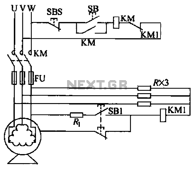
A voltage leakage protection circuit utilizing a resistive element as an auxiliary neutral point is illustrated in the accompanying figure. When selecting the resistance, it is essential to consider both the resistance value and power consistency. The described voltage leakage...
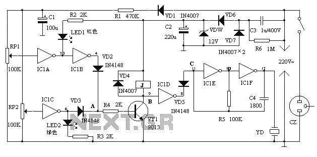
The alarm protection can trigger a sound and light alert when the mains voltage exceeds or falls below a predetermined threshold. It automatically disconnects the electrical power supply without damaging the electrical protection. The device is compact, fully featured,...
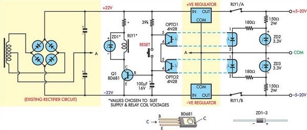
This circuit was designed to protect a dual rail power supply from shorts across the two rails. It uses an optocoupler to monitor each supply rail, with the internal LEDs powered from ZD2 and ZD3 and the associated resistors....
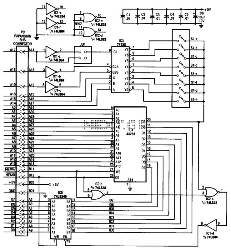
This circuit protects a PC by requiring a password to boot. After three unsuccessful attempts, the computer must undergo a cold reboot before the password can be attempted again. Software for this system is available; consult the reference for...
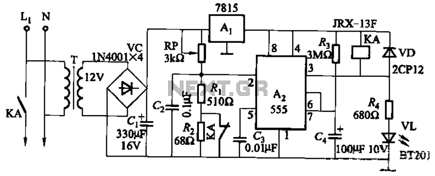
This circuit is applicable in refrigerators and other protective devices. It employs a 7815 three-terminal voltage regulator integrated circuit and an NE555 timer IC configured as a one-shot circuit for delay control. When the voltage drops below 180V, relay...