
Passive mixer

The circuit functions by taking two separate stereo input signals and merging them into a single monaural output. The primary components involved are the switch K1, resistors R2 and R3, and the input and output connectors.
K1 serves as a switch that isolates the left and right channels of the stereo input. When activated, it allows the signals from both channels to pass through while preventing interference between them. This isolation is crucial for maintaining signal integrity and ensuring that the final output is a true representation of the combined audio signals.
Resistor R2 is connected in such a way that it further isolates the two circuits, ensuring that any potential cross-talk or interference is minimized. This resistor plays a vital role in maintaining the quality of the audio output by reducing unwanted noise that can occur when combining signals.
Resistor R3 is used to adjust the level of the combined output signal. By varying the resistance, the amplitude of the output can be controlled, allowing for a balanced audio experience. This control is particularly important in applications where the output needs to match the input levels of other devices or systems, ensuring compatibility and optimal performance.
Overall, this circuit is a straightforward yet effective solution for combining stereo audio signals into a single monaural output, making it suitable for various applications in audio processing and signal routing.This simple circuit can be used to combine stereo signals to produce a monaural output K1 and R2 isolate both circuits and R3 controls the level of the combined output signal.
Related Circuits
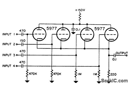
This circuit is utilized for combining four distinct positive-polarity marker pulses in a radar system. The reference for this information is the "Handbook Preferred Circuits Navy Aeronautical Electronic Equipment," Volume 1, Electron Tube Circuits, published in 1963, page N4-1. The...
A lot of friends asked me to draw a more shrunk circuit 2-ch mixer, which will contain also, operation CROSSFADER. The circuits can be modified and added also other channels, repeating basic that I give. It can be added...
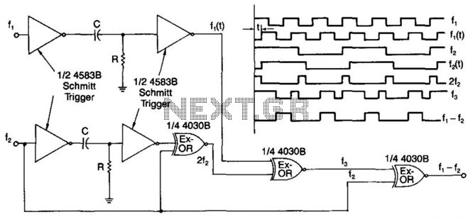
A simple digital mixer uses two dual-Schmitt triggers (4583B) and three exclusive-OR gates, incorporating an RC time-delay circuit to allow for easy adjustment of the output signal pulse width. The exclusive-OR gates can also function independently as a symmetrical...
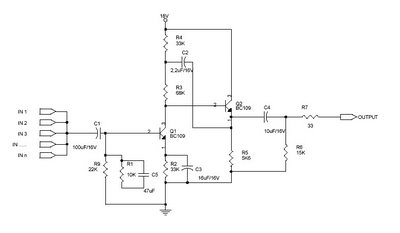
This circuit, referred to as an Audio Mixer, is a very simple design that utilizes easily obtainable components. Typically, audio mixer circuits require several integrated circuits (ICs); however, this particular audio mixer circuit relies solely on transistors as its...
The circuit is designed to provide two channels on a stereo mixer intended for microphones, incorporating a crossfader operation. It utilizes the NE5532 integrated circuit. The stereo mixer circuit features two independent channels, each capable of handling microphone input signals....
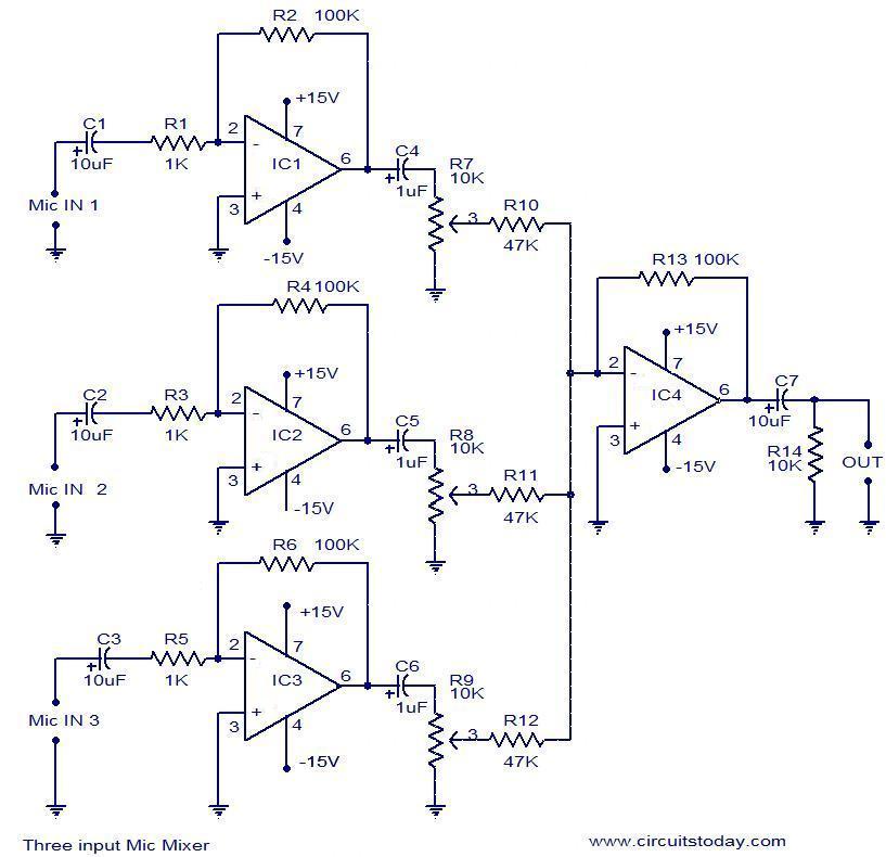
This document outlines a simple three-input microphone mixer circuit utilizing the widely used uA741 integrated circuits (ICs). Four uA741 ICs are employed in this design. IC1, IC2, and IC3 function as preamplifiers, each providing a gain of approximately 40...