
Password electronic doorbell 2
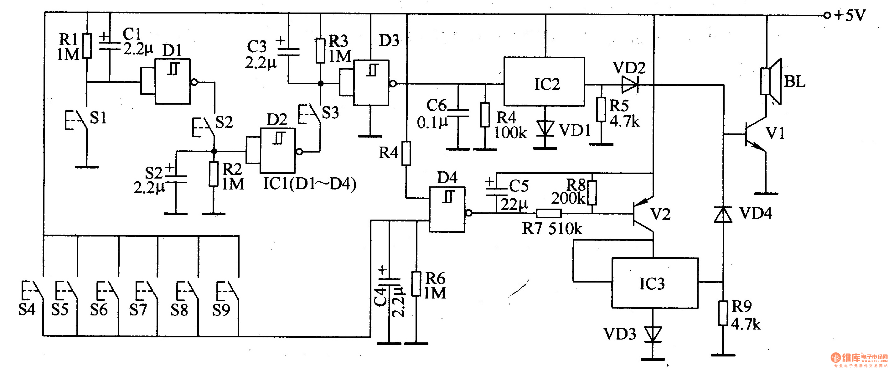
The password electronic doorbell circuit operates by utilizing a trigger mechanism that responds to user input via buttons S1 to S9. Each button corresponds to a specific password, allowing for a unique identification method for doorbell activation. The trigger circuit employs four NAND gate Schmitt trigger ICs, which provide a stable output signal in response to the button presses. The Schmitt trigger configuration ensures that the circuit is less susceptible to noise and provides a clean transition between high and low states.
The external RC components, consisting of resistors and capacitors, are used to set the timing characteristics of the trigger circuit. This timing can determine how long the doorbell remains activated after a button is pressed, ensuring that the music playback does not terminate prematurely.
The music generating circuit is responsible for producing the sound output when the doorbell is activated. Integrated circuits IC2 and IC3 are typically configured as sound generators, which may use techniques such as waveform synthesis or playback of pre-recorded audio samples. The transistors in this section serve as amplifiers to drive the speaker, ensuring that the sound produced is loud enough to be heard clearly.
Overall, the design of this password electronic doorbell circuit emphasizes both functionality and user interaction, providing a modern approach to traditional doorbell systems while ensuring a user-friendly experience.The password electronic doorbell circuit is composed of the trigger circuit and music generating circuit, and it is shown in Figure 3-119. Trigger circuit is composed of the buttons S1-S9, four NAND gate Schmitt trigger integrated circuit IC1 and the external RC components.
Music generating circuit is composed of the integrated circuits lC2 and 1C3, transist.. 🔗 External reference
Related Circuits
Adding this combination audio circuit, as illustrated in figure 14-38, to the automatic rhythm generator of electronic musical instruments fulfills the players' demand for incorporating drum and cymbal audio, enhancing the overall performance effect. The diagram indicates that the...

This circuit utilizes a CMOS integrated circuit to perform dual functions. The first two inverters serve as a digital audio oscillator, while the third inverter functions as a low-gain linear audio amplifier. The frequency of the oscillator increases with...

The input capacitor is used for low-frequency cut-off, with a standard value of 0.1 µF, resulting in a cut-off frequency of approximately 16 Hz. The input capacitor plays a critical role in electronic circuits, particularly in signal processing and audio...
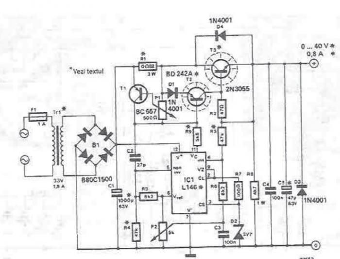
An adjustable laboratory power supply capable of providing an output voltage range from 0 to 60 volts can be constructed using the provided circuit diagram. This power supply can utilize the LM723 chip for lower voltage applications or, for...
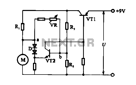
The electronic circuit for steady speed motor applications utilizes an automatic remote control system to regulate the motor power supply, thereby achieving consistent speed control. The circuit diagram illustrates a DC motor connected to the system. Given that the...
This circuit is a modified Hartley oscillator that incorporates additional components. It utilizes a small audio transformer, specifically the LT700 model. The primary winding is center-tapped with an impedance of 1 kΩ at 1 kHz, while the secondary winding...
Warning: include(partials/cookie-banner.php): Failed to open stream: Permission denied in /var/www/html/nextgr/view-circuit.php on line 713
Warning: include(): Failed opening 'partials/cookie-banner.php' for inclusion (include_path='.:/usr/share/php') in /var/www/html/nextgr/view-circuit.php on line 713